NESPi Project Part 3 – Video output and DC input board
In my opinion this is the hardest and most boring part of the whole project, but the result will be rewarding! In this post I will show you how to use acrylic plastics to make a board where we can glue extensions cables in a practical and good-looking way.
Quick Guide
- Saw pieces of acrylic plastics to fit the original input and output board place.
- Glue extensions cable to the acrylic board.
- Get exact measurements through the whole process!
Step 1 – Cut and drill acrylic plastics to fit the bottom case
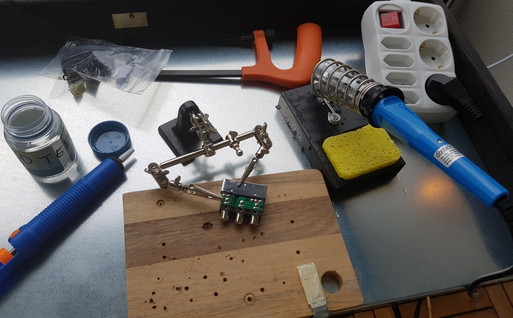
Here is my workspace:
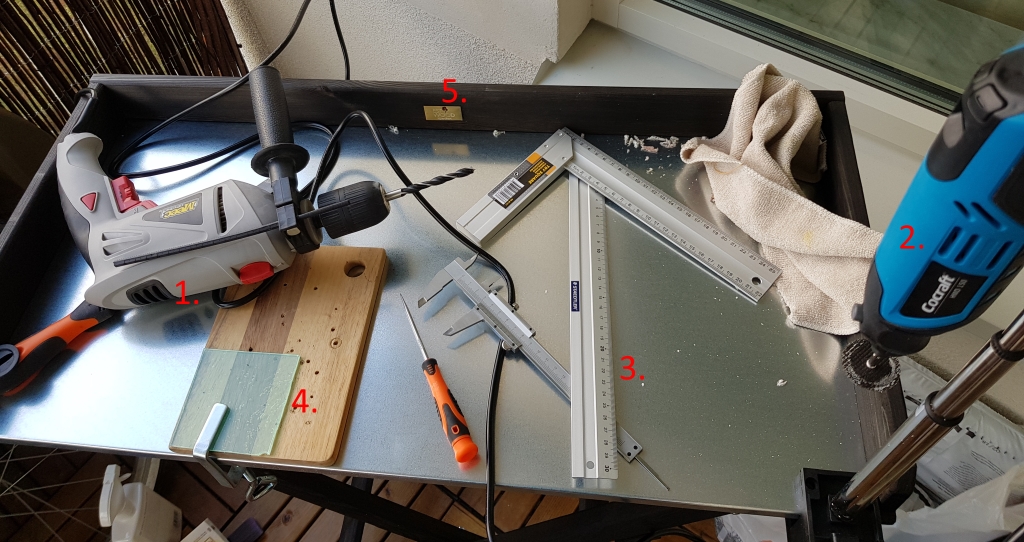
- Tool for drilling.
- A multi handheld tool I use for cutting and drilling.
- Tools for accurate measurements.
- A good place to drill and cut without damaging the work bench.
- A work bench that folds together (remember that I live in a small apartment, most of my work I do on the balcony).
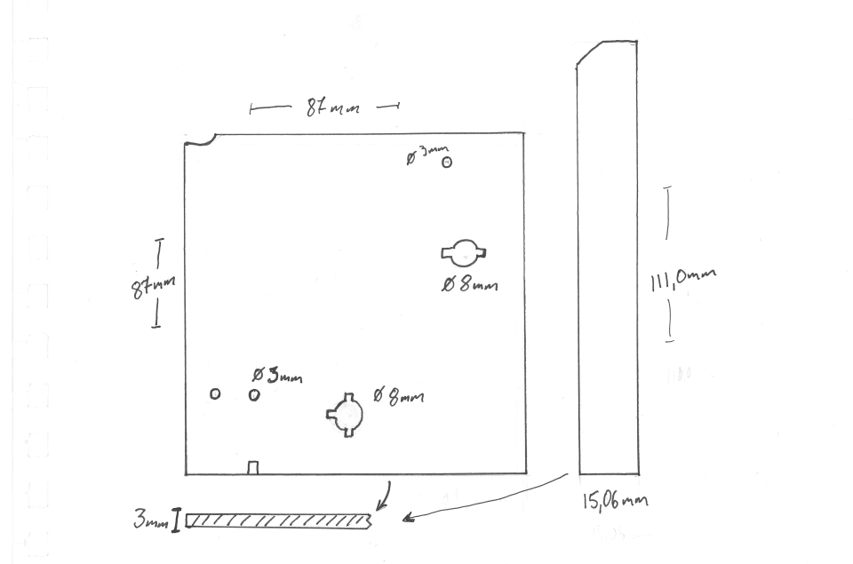
The goal of this step is to make something like this:
Step 2 – Glue the pieces together and ad the DC input
After I cut the acrylic plastic pieces, I glued them together with adhesive made for acrylic plastics: Acrifix. Then, I measured and glued the micro USB extension cables for DC input to the board:
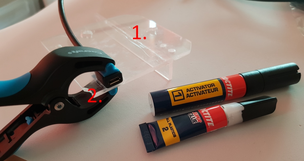
- Working with acrylics I use Acrifix. (I know there are soft welding techniques out there but it’s hard for me to get the right tools and chemicals. They are not shipped over seas so easily due to highly flammable compounds.)
- Cables are made of a type of plastics that are hard to glue. I use a two-compound glue specially made for all plastics, including cables. (See image).
NOTE! I don’t give exact measurements in this post, because it is hard to tell depending on which extensions cables you choose. You must figure it out on you own what fits and looks best in you NES. At least you have some pointers and inspiration here.
Step 3 – Video and sound output
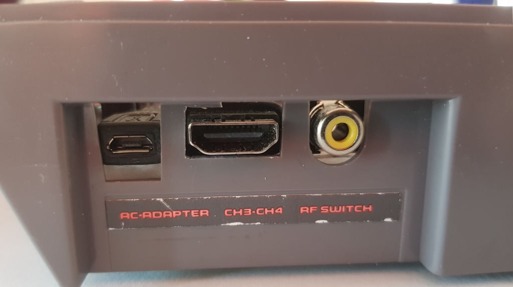
After I was finished with the micro USB cable which will provide power to the Raspberry Pi, I moved on to the HDMI cable (50cm long):
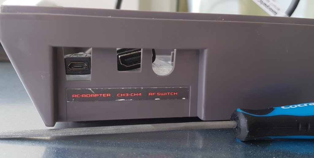
As you can see, there is no way to fit the HDMI cable in one of the original wholes. Remember the two principles from the first blog post in this series?
- The finished console should look and feel authentic.
- Minimal or no damage to the original hardware.
Well, I’m not happy about it but here I don’t see another option than to compromise the two principles. Look and feel authentic would be to put in a cable in the back of the NES to connect it to a TV screen, but to make it fit I must make one of the holes wider.
Note. I hope I don’t need to do something like this in the near future, that the next Raspberry Pi will support video via USB-C or something like that.
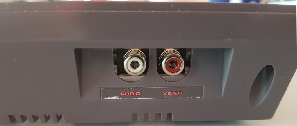
I moved on to make the RCA Outputs, I used an old scart adapter:
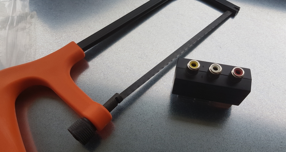
My setting:
I had to desolder and saw the board in two halfs.
This is how the acrylic board looks like with everything attached to it (micro USB extension, HDMI extension and RCA output):
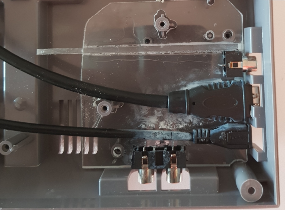
Note. The with flammable stains are from the reaction between the all-plastics-glue and the acrylic.
Step 4 – Conclusion
This is how the finished board with extension cables looks like from the back and from the side of the case: