NESPi Project Part 4 – The NES controller port and protocol
This NESPi will utilize the original controller ports and original NES controllers. The feeling is in the original controllers! To accomplish this, we will interface the original NES controller protocol and use an Arduino pro micro controller to convert the signals to keyboard presses, which we later can map to the emulators running on the Raspberry Pi.
If you don’t know anything about programming or electronics it will be hard for you to follow along in this post. But don’t give up! There are excellent toolkits and tutorials out there for learning how to program microcontrollers like the Arduino. My advice is that you buy a kit with various components and one that comes with a book. Do all the exercises and you will be able to understand everything in this blogpost! I will also provide two working versions of the code for the interface, one easy to understand but not so “clean” and one proper code that will work like a library.
Quick Guide
- Know the pinout, read all documentation you can find.
- Familiarize with the protocol, read all documentation you can find.
- Use a logic analyser to learn about the protocol in detail.
- Set up a breadboard for testing.
- Write an easy to understand program or pseudocode.
Step 1 – The pinout
Browse the web and read documentation about the pinout. This is what I found out:
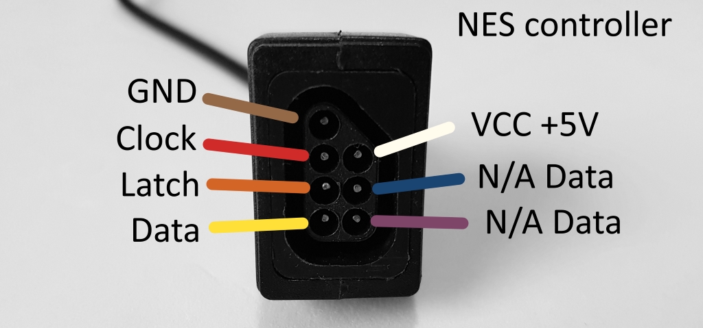
Looking at the face of the female port on the console or an extension cable.
Note. The colour scheme is from an original NES console. Your console or extension cable may have other colours.
- GND – Ground.
- Clock – The clock/pulse to control the state of the IC in the NES controller.
- Latch – Resets/starts the IC.
- Data – Data is transmitted/readable on this wire.
- Vcc – +5v.
- N/A Data – Data wires for controllers like the Zapper. Light guns won’t work with emulators or modern TVs/monitors.
Info. I’m sad to tell you this: there is no way to make a light gun work with modern TV screens or with the emulators I’m going to use. It has to do with the technology CRT screens was based upon. It simply can’t be done (not with my knowledge at least).
Step 2 – understanding the protocol
As you can see in step 1, The NES controller has 7 wires. Two of the wires are only for the light gun and other peripherals. Another two wires are for ground (-) and vcc (+). That leaves 3 wires in all to keep track on eight different button presses. As you can guess, it won’t be a wire for each button. The NES controller has a small IC inside (a shift register), which keeps track of the button states with the need of only 3 wires. Now I will show you how this works and how I learned about it:
First, I sat up a lab environment:
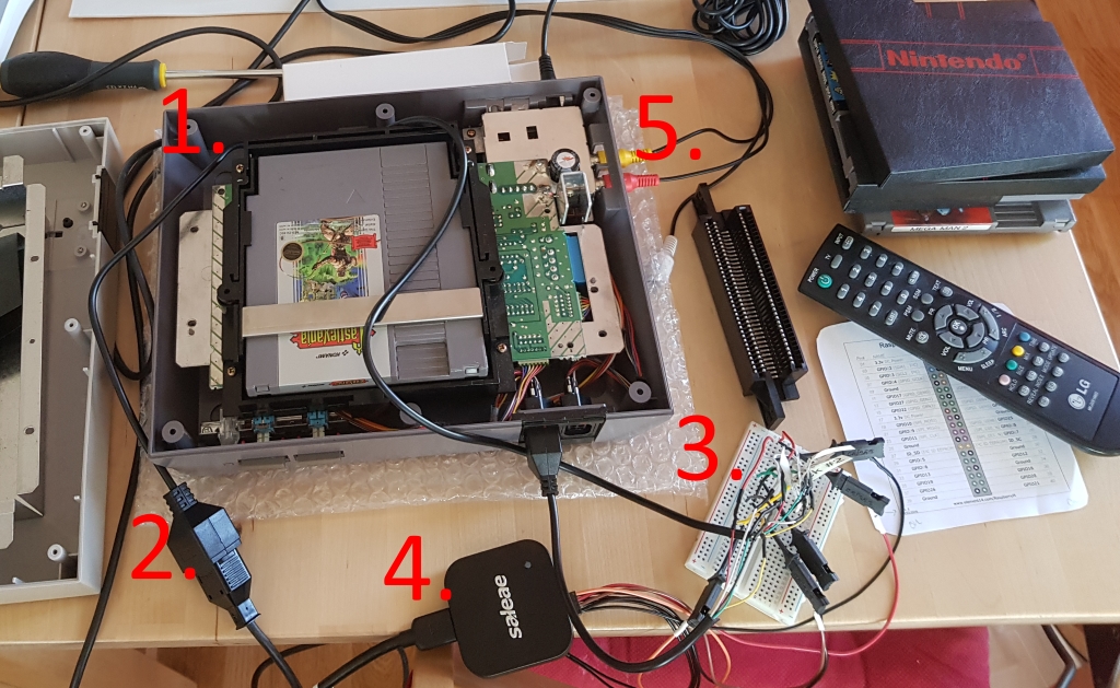
- This is an original NES. At first, I didn’t get a proper picture. So, I replaced the connector and it was working again.
- I bought an after-market extension cable and cut it in two. I extended each wire, so I could connect them via a breadboard. With this approach a could play on an original NES, while exposing the cables for the logic probes (#3), without damaging any original hardware.
- Logic probes are connected to each wire from the NES controller to the logic analyser (#4).
- I use a logic analyser from Saleae. It is connected to a computer which runs the software to capture the signals going through the wires on the breadboard (#3).
- The NES is connected to a small TV screen, so I can see what I’m doing in the game while I am recording the NES controller protocol.
Info. Once again, I am reminded about how little space I have to perform my labs on. This is a small table that is not much bigger than you can so in the image above. The TV screen and computer are cut off picture.
Now we are going to look at what was recorded:
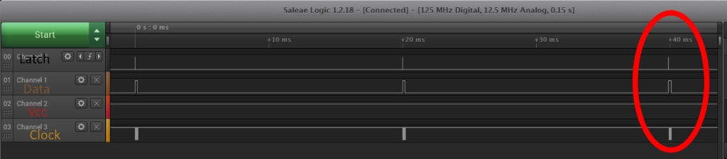
The image above is a snippet from the Saleae GUI. As you can see, each ~20ms something is happening on the wires. This is what’s going on:
- Approximately each 20 milliseconds the latch goes high to activate/reset the integrated circuit (IC) in the NES controller.
- After that the clock goes from high to low and back to high, it does these 8 times (8 cycles/pulses).
- After the latch pulse and between each clock you can read the data wire. If it is low, a button is pressed.
In the image above, we can’t really see the details so let’s zoom in to the action in the red ellipse:
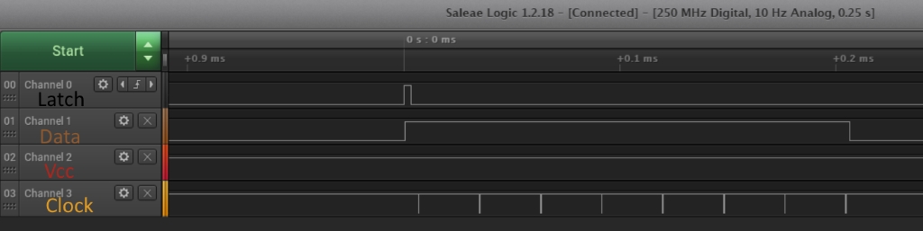
This is how the zoom in looks like from the previous image.
Info. The Saleae GUI is very intuitive. You use the scroll wheel to zoom in and out. You can also change colours and rename the channels if you’d like. This time, I wrote the names manually with an editing tool for enhanced visibility for this blog post.
In the image above you can see that:
- When the latch goes high the IC starts sending data.
- Data wire goes high right after latch goes high. It later drops to low after the last clock pulse.
- Clock drops from high to low, not the opposite as many tutorials show, although practical it doesn’t really matter.
- In the example above none of the buttons are pressed, therefore the data wire is high through the whole transmission.
By pressing one button for each recording I can find out which button press is possible to read when. Let’s start with the START button:
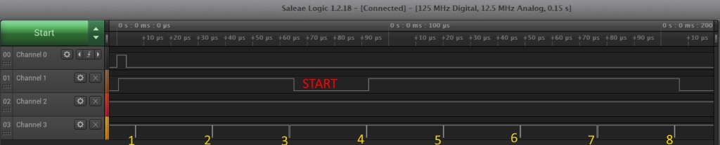
This is a recording when ONLY the start button is pressed.
Notice:
- After latch, the data wire goes high, NOT after the first clock.
- The data wire goes back to default low after the 8th clock.
- If the data wire is low after the 3rd clock, it means that the start button was pressed.
Let’s apply this method of making a recording when pushing one button at a time:
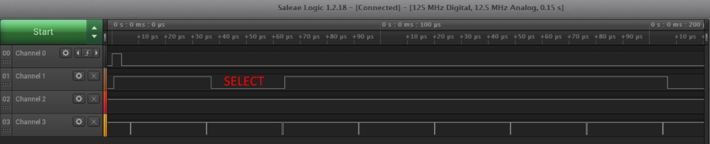
SELECT is pushed when data wire is low after the 2nd clock pulse.
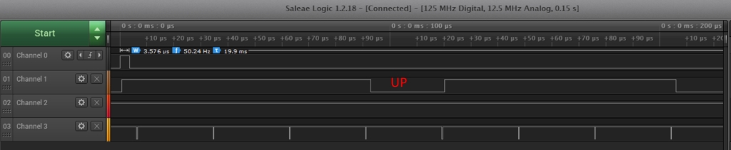
If the data wire is low after the 4th clock, that indicates that the UP button is pressed on the D-pad.
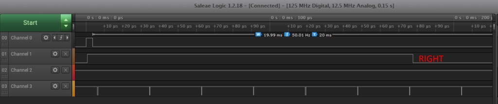
When the right button is pressed on the D-pad.
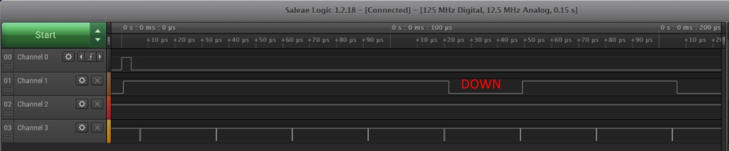
When the down button is pressed on the D-pad.
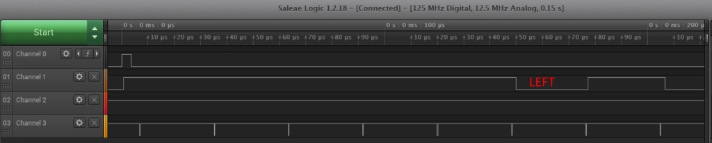
When the left button is pressed.
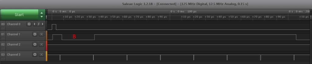
When the B button is pressed.
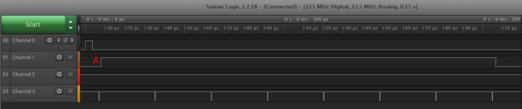
When the A button I pressed.
Note. It can be tricky to see that a button is pressed here. The A button press is indicated if the data wire is low directly AFTER the latch pulse and BEFORE the first clock pulse!
Here is a final example of how it looks like when several buttons are pressed at the same time:
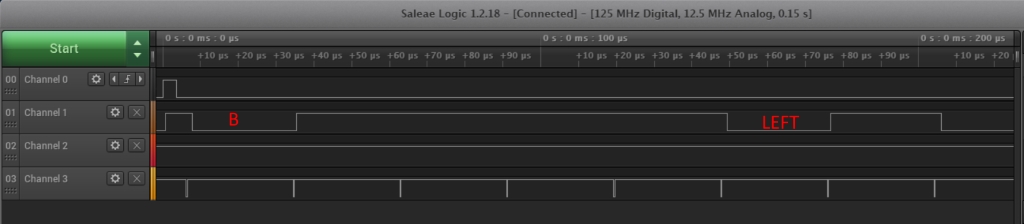
In this example button B and LEFT are pressed simultaneously.
Summary – understanding the protocol
Now we understand the protocol and know all the positions and when to read each button press:
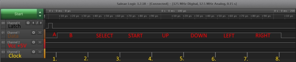
In this summary, only the A button is pressed. The buttons are written on the data wire on the position it would correspond to if the wire was low.
Step 3 – Set up a breadboard for testing
To create the breadboard for testing I am using the following parts:
- Arduino Pro Micro +5V.
- 2 aftermarket extension cables.
- Heat shrink tubes.
- Wires for breadboard testing (not copper), you can stick them into the breadboard.
- Everything for soldering.
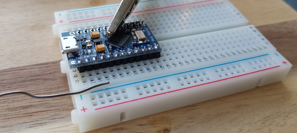
Solder pins to the microcontroller.
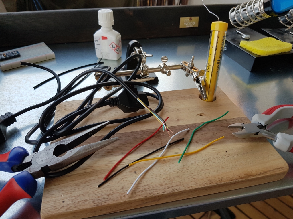
Solder extension cables.
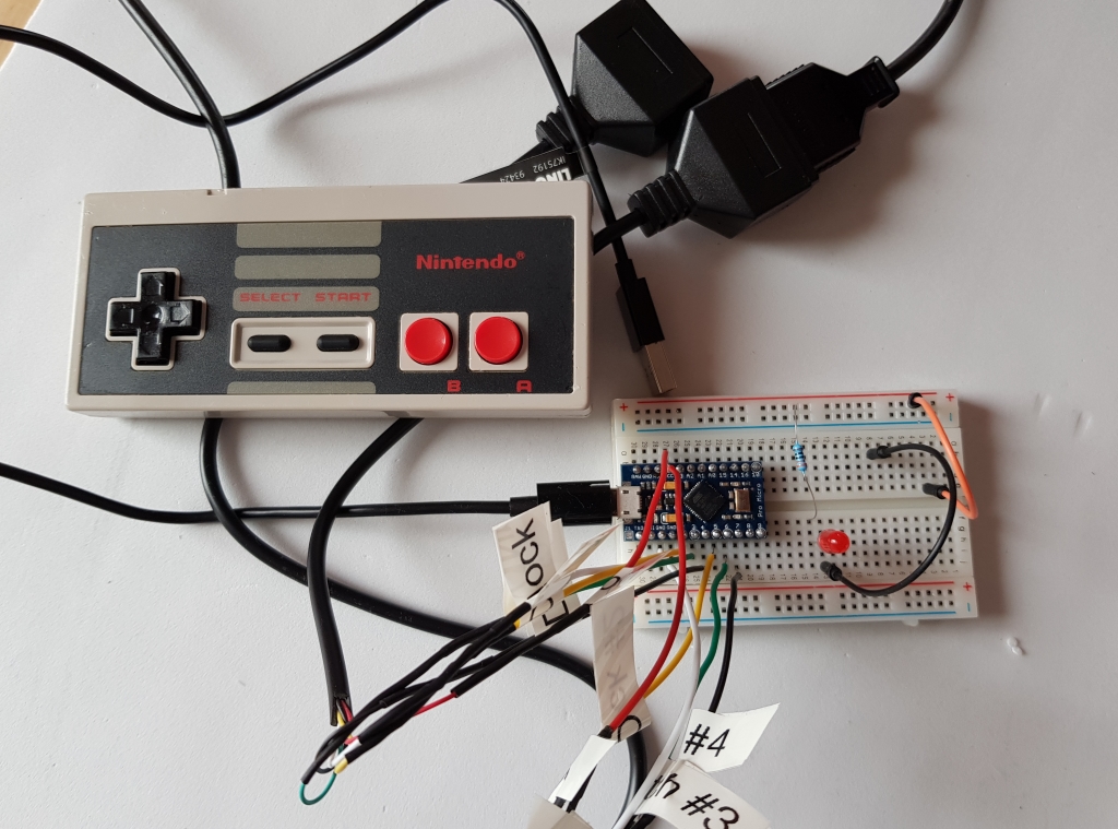
Breadboard with extension cables, ready for testing. I also labelled the wires, clock, data, latch etc.
Step 4 – The Code, light version (pseudocode)
It’s time to translate the understanding of the protocol into code. The goal is to convert button presses on a NES controller into emulated keyboard presses that we later can map to actions in the emulator e.g. the key press ‘j’ means that player 2 hits the B button, that will cause Luigi to jump.
Note. In these code examples I’m using an Arduino Pro Micro that can emulate a keyboard out of the box. You only need to include the keyboard library, which comes with the IDE installation of Arduino. There is a great documentation at: https://www.arduino.cc/reference/en/language/functions/usb/keyboard/ .
EDIT 2018-09-22. The first versions of the two code examples didn’t used a pullup resistor on the data input pins. It caused random readings when there was no controller present, plugged in to the port. It is now changed. Any further bugs and I will update the code examples again. Note, that I’m no expert in the field of electronics or programming, I am also learning a lot while doing these projects. Conclusion is that you should always use a pullup or pulldown resistor with data input pins to avoid floating values or random readings. These kinds of resistors will guarantee that, when there is nothing to read on the wire, the signal will remain at 5V(pullup) or 0V(pulldown). Arduino has a built-in pullup resistor on most of the pins, which can be accessed via code, so no need for a physical resistor. I use the build-in pullup resistor in the examples now.
This code is a simple implementation of the NES controller protocol. It contains repetitive code and unnecessarily function calls. It is made for educational purposes. People with little knowledge in programming should be able to follow along and then improve the code by them self, with for loops, last button state check etc.
NESControllerLightVersion.ino:
/* -NESControllerLightVersion -
 * Converts button presses on a NES controller into emulated keyboard presses.
 * This code is a simple implementation of the NES controller protocol.
 * It contains repetitive code and unnecessarily function calls. It is made for educational purposes.
 * People with little knowledge in programming should be able to follow along and then improve the code by them self,
 * with for loops, last button state check etc.
 * Created by Raspberryfield.life August 2018
 */
 /* *NES Controller Pinout Console (Female)*
  *          _
  * GND   - |O \
  * Clock - |O O| - VCC (5v)
  * Latch - |O O| - Data N/A (Zapper etc.)
  * Data  - |O O| - Data N/A (Zapper etc.)
  *         ----
  */
  /* *NES protocol ~20ms between each data cycle*
   *           _
   * Latch - _| |___________________________________________________
   *         ______   ___   ___   ___   ___   ___   ___   ___   ____Note1. Last clock does nothing.
   * Clock -       |_|   |_|   |_|   |_|   |_|   |_|   |_|   |_|
   *            _____________________________________________
   *  Data - __|_A_|_|_B_|_|Sel|_|Sta|_|Up_|_|Dow|_|Lef|_|Rig|______
   *  Note2. After Latch goes HIGH, Data goes HIGH and becomes active low (if a button is pushed
   *  after clock signal, data wire reads low).
   *  Note3. State of A button is read after latch and before first clock.
   */
#include <Keyboard.h>
//Constants for the pinout in the pro micro board (+5V).
const int nesClock = 2;
const int nesLatch = 3;
const int nesData = 4;
void setup() {
  // put your setup code here, to run once:
  pinMode(nesData,INPUT_PULLUP);
  pinMode(nesClock,OUTPUT);
  pinMode(nesLatch,OUTPUT);
  digitalWrite(nesClock, LOW);
  digitalWrite(nesLatch, LOW);
  Keyboard.begin();
}
void loop() {
  // put your main code here, to run repeatedly:
  //Pulse Latch wire:
  digitalWrite(nesLatch, HIGH);
  digitalWrite(nesLatch, LOW);
  //After latch pulse, check if A button is pressed:
    //If low, call library Keyboard function press and set a char for it.
      //Else release all key presses for that char.
  if(digitalRead(nesData)==LOW){
        Keyboard.press('a');
      }else{
        Keyboard.release('a');
      }
  // 1st clock.
  digitalWrite(nesClock, LOW);
  digitalWrite(nesClock, HIGH);
  //After 1st clock, check if B button is pressed:
  if(digitalRead(nesData)==LOW){
        Keyboard.press('b');
      }else{
        Keyboard.release('b');
      }
  // 2nd clock.
  digitalWrite(nesClock, LOW);
  digitalWrite(nesClock, HIGH);
  //After 2nd clock, check if SELECT button is pressed:
  if(digitalRead(nesData)==LOW){
        Keyboard.press('c');
      }else{
        Keyboard.release('c');
      }
  // 3rd clock.
  digitalWrite(nesClock, LOW);
  digitalWrite(nesClock, HIGH);
  //After 3rd clock, check if START button is pressed:
  if(digitalRead(nesData)==LOW){
        Keyboard.press('s');
      }else{
        Keyboard.release('s');
      }
  // 4th clock.
  digitalWrite(nesClock, LOW);
  digitalWrite(nesClock, HIGH);
  //After 4th clock, check if UP button is pressed:
  if(digitalRead(nesData)==LOW){
        Keyboard.press('u');
      }else{
        Keyboard.release('u');
      }
  // 5th clock.
  digitalWrite(nesClock, LOW);
  digitalWrite(nesClock, HIGH);
  //After 5th clock, check if DOWN button is pressed:
  if(digitalRead(nesData)==LOW){
        Keyboard.press('d');
      }else{
        Keyboard.release('d');
      }
  // 6th clock.
  digitalWrite(nesClock, LOW);
  digitalWrite(nesClock, HIGH);
  //After 6th clock, check if LEFT button is pressed:
  if(digitalRead(nesData)==LOW){
        Keyboard.press('l');
      }else{
        Keyboard.release('l');
      }
  // 7th clock.
  digitalWrite(nesClock, LOW);
  digitalWrite(nesClock, HIGH);
  //After 7th clock, check if RIGHT button is pressed:
  if(digitalRead(nesData)==LOW){
        Keyboard.press('r');
      }else{
        Keyboard.release('r');
      }
  // 8th clock.
  digitalWrite(nesClock, LOW);
  digitalWrite(nesClock, HIGH);
  delay(20);//Wait 20ms for next loop.
}//End loop
Step 5 – The Code, library version
Note. If you are not used to programming or electronics I would recommend that you follow step 4. Look at step 5 as a future challenge.
The code presented here can be turned into a library. To use it is very simple and you hardly need to code anything.
Compared to the light version this code doesn’t repeat itself and it doesn’t call Keyboard.release() unnecessarily times. To accomplished this, the code always compares the last cycle of all possible buttons states with the next, like the protocol every 20 milliseconds. The states are stored and represented as bits in a byte. Byte wise operators are used for comparison. 1 means that the button is pressed and 0 means not pressed. The bits are represented from the data wire as MSB, most significant bit first.
Here is a great tutorial from Arduino how to create libraries: https://www.arduino.cc/en/Hacking/LibraryTutorial . Follow this tutorial, and with some intermediate prior knowledge of electronics and programming you should be able to understand the following code:
NEScontroller.h :
/*
	NEScontroller.h - Library for interfacing one or several NES controllers.
	Created by Raspberryfield.life August 2018
*/
#ifndef NEScontroller_h
#define NEScontroller_h
#include "Arduino.h"
class NEScontroller
{
public:
	NEScontroller(int clockPin, int latchPin, int dataPin, char *commandsController);
	int begin();
private:
	int _clockPin;
	int _latchPin;
	int _dataPin;
	char *_commandsController;
	byte _lastDataCycle;
	byte _currentDataCycle;
	void pulseWire(int wire, bool pulse);
	byte dataReadnUpdate(int dataWire, byte dataByte, byte bitValue);
};
#endif
NEScontroller.cpp :
/*
	NEScontroller.cpp - Library for interfacing one or several NES controllers.
	Created by Raspberryfield.life August 2018
*/
#include "Arduino.h"
#include <Keyboard.h>
#include "NEScontroller.h"
NEScontroller::NEScontroller(int clockPin, int latchPin, int dataPin, char *commandsController)
{
	pinMode(clockPin, OUTPUT);
	pinMode(latchPin, OUTPUT);
	pinMode(dataPin, INPUT_PULLUP);
	digitalWrite(clockPin, HIGH);
	digitalWrite(latchPin, LOW);
	_clockPin = clockPin;
	_latchPin = latchPin;
	_dataPin = dataPin;
	_commandsController = commandsController;
	_lastDataCycle = 0b00000000;
	_currentDataCycle = 0b00000000;
}
int NEScontroller::begin()
{
	/*
	* Start by putting the last read data cycle to lastDataCycle variable and
	* then put current DataCycle to zero, ready for a new state read of data (button pushes).
	*/
	_lastDataCycle = _currentDataCycle;
	_currentDataCycle = 0b00000000;

	//Second pulse the latch wire, it resets the IC in the NES controller.
	pulseWire(_latchPin, 1);
	//After latch it is possible to read the A button state.
	_currentDataCycle = dataReadnUpdate(_dataPin, _currentDataCycle, 0b10000000); //0b10000000 = 128, "A" button.

	//Loop the other button states. After each clock it is possible to the read the values.
	for (byte byteValue = 0b01000000; byteValue>0; byteValue = byteValue >> 1) {
		pulseWire(_clockPin, 0);
		_currentDataCycle = dataReadnUpdate(_dataPin, _currentDataCycle, byteValue);
		//delayMicroseconds(2);//Maybe not needed.
	}//End loop.

	//Finish of with the last clock pulse (I don't think it is actually doing anything).
	pulseWire(_clockPin, 0);//One extra (8th) clock is required to follow protocol.
	//Now we are finished with reading the button states.

	//It's time to do something with the data collected:
	//If XOR of current and last is not zero, that means that there is a change in button press/release. Only then Something has to be done.
	if (int(_currentDataCycle ^ _lastDataCycle) != 0) {
		//Start checking what change has occured.
		for (int i = 0; i<8; i++) {
			byte BitcurrentData = _currentDataCycle << i;
			byte BitlastData = _lastDataCycle << i;
			if (int((BitcurrentData >> 7) ^ (BitlastData >> 7)) != 0) {
				if (BitcurrentData >> 7 != 0) {
					//Serial.print("Pushed [i]: ");Serial.print(i);
					//Serial.println();
					Keyboard.press(_commandsController[i]);
				}
				else {
					//Serial.print("Released [i]: ");Serial.print(i);
					//Serial.println();
					Keyboard.release(_commandsController[i]);
				}//End if/else push or release.
			}//End if check singel bit.
		}//End for loop all bits.
	}//End if  there is a change at all.
}//End begin();
void NEScontroller::pulseWire(int wire, bool pulse) {
	//If second parameter positive (==1) pulse wire from low to high and back to low. Else opposite.
	if (pulse == 1) {
		digitalWrite(wire, HIGH);
		digitalWrite(wire, LOW);
	}
	else {
		digitalWrite(wire, LOW);
		digitalWrite(wire, HIGH);
	}
}//End pulseWire
byte NEScontroller::dataReadnUpdate(int dataWire, byte dataByte, byte bitValue) {
	if (digitalRead(dataWire) == LOW) {
		return dataByte | bitValue;
	}
	else {
		return dataByte;
	}
}// End dataRead
NESController.ino :
/* -NESController -
 *  NESController.ino
 * Created by Raspberryfield.life August 2018
 */
 /* *NES Controller Pinout Console (Female)*
  *          _
  * GND   - |O \
  * Clock - |O O| - VCC (5v)
  * Latch - |O O| - Data N/A (Zapper etc.)
  * Data  - |O O| - Data N/A (Zapper etc.)
  *         ----
  */
  /* *NES protocol ~20ms between each data cycle*
   *           _
   * Latch - _| |___________________________________________________
   *         ______   ___   ___   ___   ___   ___   ___   ___   ____Note1. Last clock does nothing.
   * Clock -       |_|   |_|   |_|   |_|   |_|   |_|   |_|   |_|
   *            _____________________________________________
   *  Data - __|_A_|_|_B_|_|Sel|_|Sta|_|Up_|_|Dow|_|Lef|_|Rig|______
   *  Note2. After Latch goes HIGH, Data goes HIGH and becomes active low (if a button is pushed
   *  after clock signal, data wire reads low).
   *  Note3. State of A button is read after latch and before first clock.
   */
#include <Keyboard.h>
#include <NEScontroller.h>
//declare commands Player1
//-------------------------//A         //B             //SELCT         //START   //UP      //DOWN          //LEFT          //RIGHT
char commandsPlayer1[8] = {KEY_RETURN, KEY_BACKSPACE, KEY_RIGHT_SHIFT, ' ', KEY_UP_ARROW, KEY_DOWN_ARROW, KEY_LEFT_ARROW, KEY_RIGHT_ARROW};
//Parameters: #clockPin, #latchPin, #dataPin, KeyCommands[]
NEScontroller player1(2,3,4, commandsPlayer1);
//declare commands player 2 and inti player 2
char commandsPlayer2[] = {'j', 'h', 'f', 'g', 'w', 's', 'a', 'd'};
NEScontroller player2(5,6,7, commandsPlayer2);
void setup() {
  //Setup is created by the class when init a player. No need for setup here.
}
void loop() {
  // put your main code here, to run repeatedly:
  player1.begin();
  player2.begin();
  delay(20);
}//End Loop
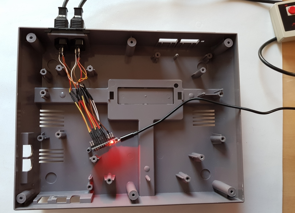
Step 6 – Put everything in place
The image below shows how it looks like when you have:
- Programmed the microcontroller.
- Solder wires to fit the original controller ports of the NES and the microcontroller.
- Put everything together.
NOTE! never solder on a cable attached to plastics. The heat will go through the cable and cause the plastic to melt! (don’t ask me how I know this).
One Response to “NESPi Project Part 4 – The NES controller port and protocol”
miguel angel
muy buena explicación y el equipo adecuado para detectar las posiciones de ños cables del mando.