NESPi Project Part 5 – Power and Reset button board
In this blogpost I will show how to use the board with the LED and power button and reset button. We will make all the necessarily preparation, so we later can easily connect it to the Pi.
Quick Guide
- Desolder the original cables and the LED.
- Retrobright the buttons if needed.
- Make new wire and cable extensions to fit the Raspberry Pi.
- Replace the LED with a new one.
- Mount the board to the bottom NES case.
Step 1 – Desolder the original wires and the LED
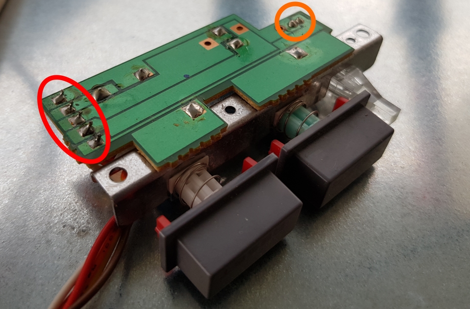
Desolder the original wires (red) and the LED (orange).
Info. The buttons were quite yellowed, so I had to retrobright them. For more details about retrobright, see blogpost “NESPi project part 1 – the Case” in this series.
Step 2 – Make new wires and cable
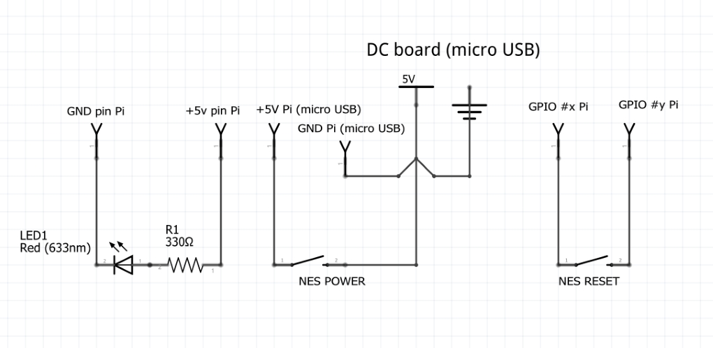
This is how it will be wired:
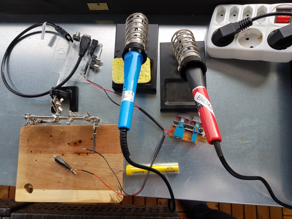
Back to the workbench:
Info. All wires ~35cm. Ground wire 2x 35cm.
Note. Normally black wire means negative / ground and red positive voltage. Don’t take this for granted. I have worked with cables that have this swapped. Double check with a multimeter, that can handle negative voltage, to detect which wire is what. If they are swapped the multimeter will display a negative voltage value, then you know.
Wired according to the circuit diagram:
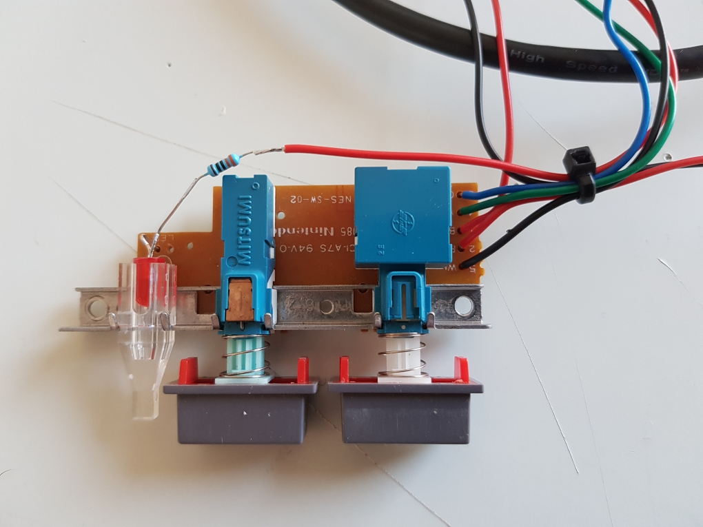
Note that the +5v wire from the Pi to the LED and the 330 Ohm resistor is not soldered on the board.
Other side:
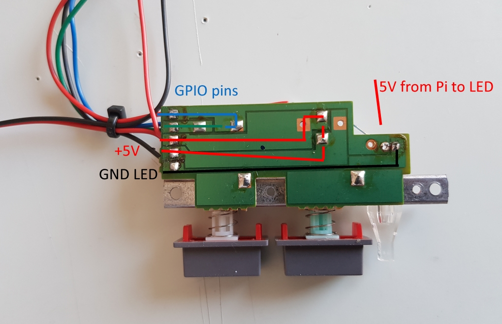
You can follow the paths on the board to see where the connections are.
Step 3 – Mount the board to the bottom case
This is how it looks like once in place:
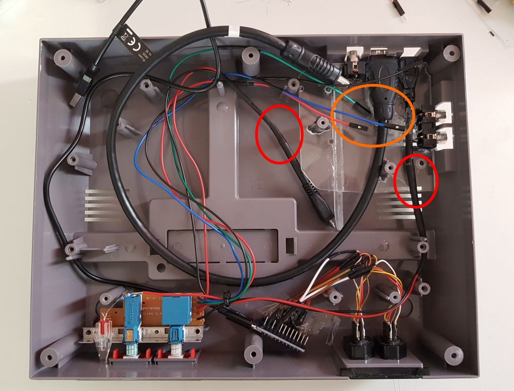
With heat shrinking tubes you can make the extensions to the micro USB female and male cables to look good (red ellipse).
The wires that will connect to the Raspberry Pi GPIO pins are extended to dupont wires for easy mounting (orange ellipse).
Note. When customizing the power supply to a Raspberry Pi you can count on voltage drop caused by the cable. The power supply I’m using says 5.1V. With the Nintendo power switch and the extended cables, I measured 5.0V. The increased resistance in the cable length and power switch is causing the voltage to drop. If the voltage drops to 4.65V you will see a warning sign (yellow flash) on the upper right corner of the screen when the Pi is running:
![]()
It indicates that the Raspberry Pi might not fully operate at lower voltage than 4.65V.
2 Responses to “NESPi Project Part 5 – Power and Reset button board”
iVirtualZero
So sad to see an NES get gutted into an emulator box.
raspberryfield
Just want to stress out that one of the purposes of this blog post is to show how to do minimal or no damage to an original NES. There is only one modification to the hardware, e few millimeters sanded down to fit the HDMI cable. This case was also missing the lid, which I replaced with a 3rd party one. The electronics were also damaged beyond repair. I would say that this one actually was brought to life again.