Arduino Basics: Push Button
You will notice in this blog that I am very much into retro gaming. I often make projects involving old hardware. One essential part of hardware is to keep track of user inputs via button pushes. Instead of explaining buttons and how to handle them in code, in each blogpost involving them, I will refer to this post. Let’s cover some basics!
Overview of Examples
- Hello World – built in LED blink
- Push Button – LED Blink (without any resistor)
- Push Button – LED Blink with pull-down resistor
- Push Button – LED Blink with pull-up resistor
- Push Button – LED Blink with internal pull-up resistor
- LED basics – external LED Blink with internal pull-up resistor
Arduino Hello World
Most of you will start with a setting like this one (I have coloured out the copper paths, how they go inside the breadboard. I think you will get the idea.):
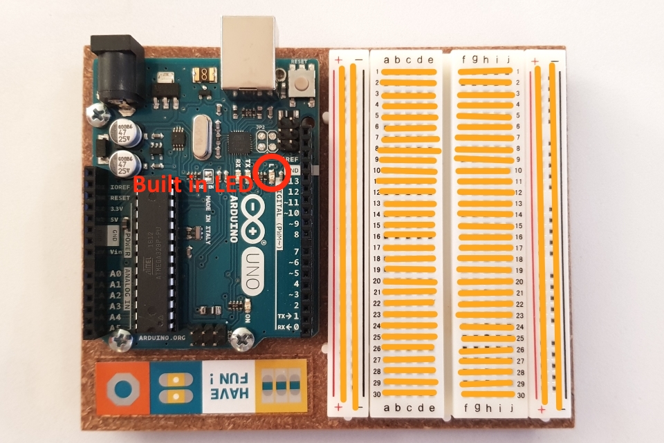
Almost all board from Arduino has a built in LED that you can control with code, here is a list: https://www.arduino.cc/en/tutorial/blink. On UNO the LED is controlled just like pin #13.
Note. Sometimes the Arduino IDE don’t automatically detect the right board and port to upload the code to. You can change this manually from the Tool settings in the IDE:
- Board change: Tools->Board->Choose the board you have.
- Port change: Tools->Port->choose port that is available.
This is the hello world of Arduino, making the on-board LED blink. No wiring is required in this example:
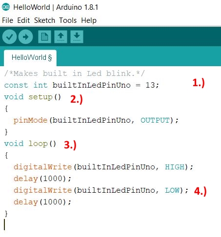
Explaining the code
All code you write in Arduino will basically look like this:
- First you declare the variables to the pins you are going to use. They are of the type constant integer, they are not supposed to be changed. You can skip them and use the number instead like this: pinMode(13, OUTPUT), but with this approach you can’t give the pins a meaningful name and it will be harder to read the code.
- In the function void setup() you will tell each pin if they are going to send out signals(current) or if the are going to read signals.
- In the function void loop() goes your code, the magic. This is a continuous loop that will always be executed as soon as the Arduino has input power.
- Common functions are digitalWrite() and delay(). Digitalwrite will tell if the pin will be high +5 volt or low 0 volt. Delay() will make a pause in milliseconds. 1000ms = 1 second. These functions are so common that you don’t even have to import a library. The Arduino IDE will recognize them for you.
HelloWorld.ino :
/*Makes built in Led blink.*/
const int builtInLedPinUno = 13;
void setup()
{
  pinMode(builtInLedPinUno, OUTPUT);
}
void loop()
{
  digitalWrite(builtInLedPinUno, HIGH);
  delay(1000);
  digitalWrite(builtInLedPinUno, LOW);
  delay(1000);
}
Back to Overview.
Problem with a naïve implementation – push button with no resistor
Let’s start with the button. This is a common push button when working with electronics:
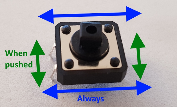
Current can always flow through in horizontal direction, upper pins and lower pins (blue arrows). But current can only go through in vertical direction (between upper and lower pins) if the button is being pushed (green arrows).
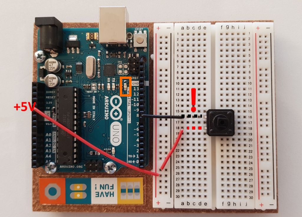
Intuitively, it is easy to think that to make something blink on a button press, you just have to wire the output pin through the button, to the input pin and everything is set!
And that is precisely what I have done here (This is a simple implementation of a button, when pressed the internal LED (pin 13) will blink):
And the code:
OnBoardLedBlink.ino :
/*Makes built in Led blink on button push.*/
/*NOTE! No pull up/down resistor used.*/
const int builtInLedPinUno = 13;
const int inPin = 8;
void setup()
{
  pinMode(builtInLedPinUno, OUTPUT);
  pinMode(inPin, INPUT);
}
void loop()
{
  if(digitalRead(inPin)==HIGH){
    digitalWrite(builtInLedPinUno, HIGH);
  }else{
     digitalWrite(builtInLedPinUno, LOW);
  }
} //END Loop
If you try this, you will notice that the led is behaving unpredictable. It might always be on, always of, flicker or turn of long after you released the button.
The reason of this unwanted behaviour is that the wire connected to the pin that is configured to read input is being left “floating”. After the button is pressed, there is still a small amount of current floating in the wire. The input pin has a hard time to evaluate this value, it might be close to 0 volt or not. It simply doesn’t really now, it might work, or it might not.
The answer to this problem is resistors! And when we use resistors to solve this problem, they are called either pull-down resistor or pull-up resistors. In the next sections I will show examples of how to use them.
Working with electronics or IT in general, we never want unpredictable behaviours! Make it a rule of thumb to always use pullup/pulldown resistors when reading inputs!
And take this in consider when coding and reading inputs. From Arduino: When working with inputs, If the pin isn’t connected to anything, digitalRead() can return either HIGH or LOW (and this can change randomly).
Back to Overview.
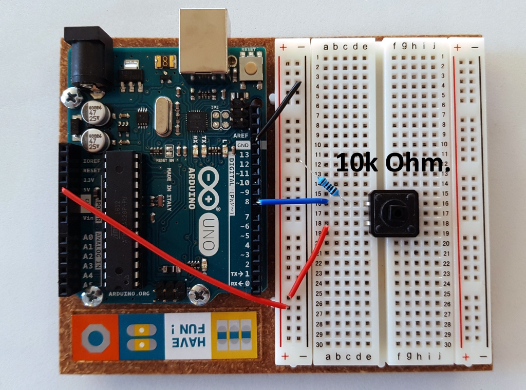
LED Blink With Pull-down Resistor
This is the first approach to solve the problem with floating values: with a pull-down resistor. Common value for a pull-down resistor and +5V is 10k ohm. Here are the schematics:
And it is the same piece of code as in the previous example:
OnBoardLedBlink.ino :
/*Makes built in Led blink on button push.*/
/*NOTE! External pull-down resistor used.*/
const int builtInLedPinUno = 13;
const int inPin = 8;
void setup()
{
  pinMode(builtInLedPinUno, OUTPUT);
  pinMode(inPin, INPUT);
}
void loop()
{
  if(digitalRead(inPin)==HIGH){
    digitalWrite(builtInLedPinUno, HIGH);
  }else{
     digitalWrite(builtInLedPinUno, LOW);
  }
} //END Loop
This time when the button is pushed, current will flow to pin 8 that detects it and the LED will light up. But when the button is no longer pushed, this time no floating current will be left. The added resistor is connected to ground. It will pull-down the remaining floating current so the pin 8 will detect 0 volt on the wire, no confusion here.
Back to Overview.
LED Blink With Pull-up Resistor
This time we will try a pull-up resistor solution to the floating value problem. But now when we have a pull-up resistor, we have to change the code, the logic is slightly different:
InternalLedBlinkPullUpResistor.ino :
/*Makes built in Led blink on button push.*/
/*NOTE! External pull-up resistor used.*/
const int builtInLedPinUno = 13;
const int inPin = 8;
void setup()
{
  pinMode(builtInLedPinUno, OUTPUT);
  pinMode(inPin, INPUT);
}
void loop()
{
  if(digitalRead(inPin)==LOW){//Now detect LOW on input wire! (Active low)
    digitalWrite(builtInLedPinUno, HIGH);
  }else{
     digitalWrite(builtInLedPinUno, LOW);
  }
} //END Loop
Here is the wiring:
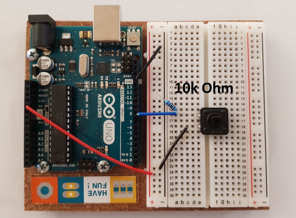
This approach is called active low. When the input wire is low (0 voltage), it means that the user has pushed a button and the LED should be turned on! The opposite is called active high, we did active high in the previous example with a pull-down resistor.
Active low is far more common approach than active high, especially among gaming controllers. So far, I haven’t encountered a controller that uses active high on the buttons.
Back to Overview.
LED Blink with internal pull-up resistor
The active low, solution with a pull-up resistor, is so common that most Arduino board have these resistors internal built in on most of the pins (check Arduino documentation for your board). Here is an example in code that does the same thing as the previous example with an external pull-up resistor. But this time we will be doing the same thing internally and we will save time, wires and resistors:
InternalLedBlinkInternalPullUp.ino :
/*Makes built in Led blink on button push.*/
/*NOTE! Internal pull-up resistor used.*/
const int builtInLedPinUno = 13;
const int inPin = 8;
void setup()
{
  pinMode(builtInLedPinUno, OUTPUT);
  pinMode(inPin, INPUT_PULLUP);//Note! Internal pull-up activated.
}
void loop()
{
  if(digitalRead(inPin)==LOW){//(Active low)
    digitalWrite(builtInLedPinUno, HIGH);
  }else{
     digitalWrite(builtInLedPinUno, LOW);
  }
} //END Loop
And this is how it is wired:
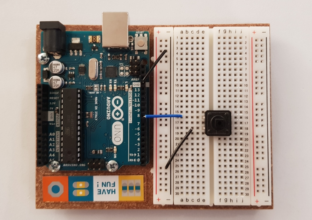
Very clean, isn’t it?
Back to Overview.
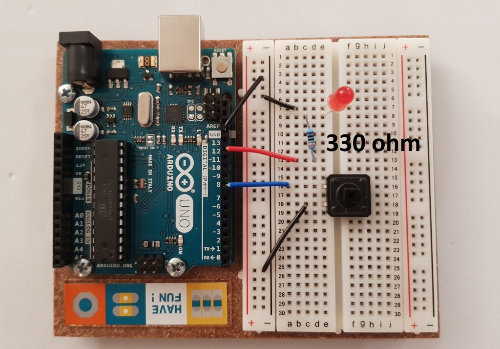
External LED Blink with internal pull-up resistor
Learning electronics, you will work a lot with buttons and LEDs as basic input and output. In this last example, I will add an external LED, just to cover the basics. This example is built upon the previous one with an internal pull-up resistor.
Let’s cover the basics of a LED:
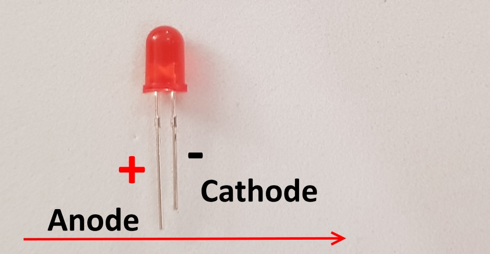
Always connect the anode (longer pin) to plus, otherwise you will burn the LED. Common resistor value when working with red LEDs and +5V is 330 ohms.
Here is the code:
ExternalLEDBlinkInternalPullUp.ino :
/*Makes external LED blink on button push.
Internal pull-up resistor used.*/
const int LED = 12;//external LED
const int inPin = 8;
void setup()
{
  pinMode(LED, OUTPUT);
  pinMode(inPin, INPUT_PULLUP);//Note! Internal pull-up activated.
}
void loop()
{
  if(digitalRead(inPin)==LOW){//(Active low)
    digitalWrite(LED, HIGH);
  }else{
     digitalWrite(LED, LOW);
  }
} //END Loop
And here is how it is connected:
Back to Overview.