Raspberry Pi – Getting Started with GPIO
Have you ever wondered what the row of pins on the Raspberry Pi is for? If ‘Yes’, this is the post to start with. This post will briefly explain what they are and provide a ‘Hello world’ example with a blinking LED.
Index
Prerequisites
- Extremely basic understanding of using the terminal in Linux.
- Extremely basic understanding of scripting/programming.
Back to Index.
Introduction
Look at this image, these are the GPIO pins:
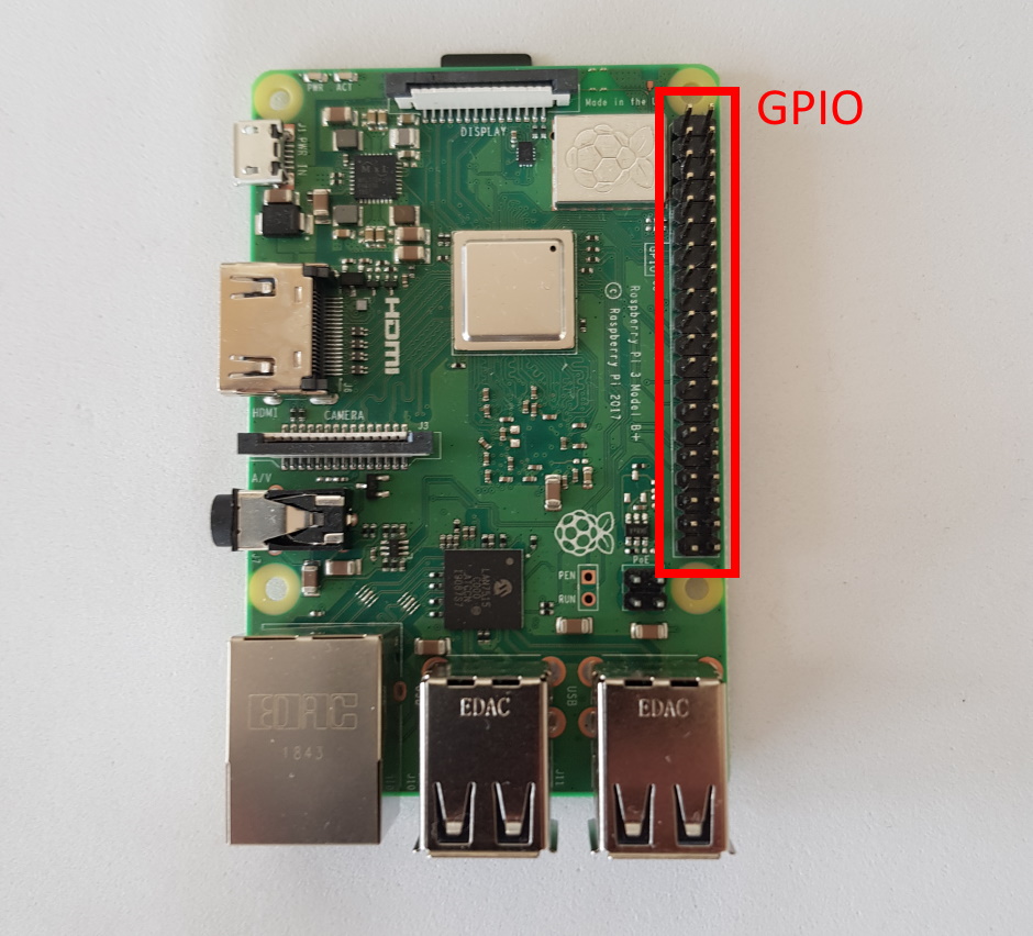
GPIO stands for general-purpose input/output, it is descriptive. Through the pins, you can send electrical signals from software and you can also receive electrical signals from other devices. This opens up almost infinite possibilities! You can control LEDs, motors, receive data from sensors, etc. It is just your imagination that will be the limits of what you can control out there!
To be able to make the next great product or innovation, you must start somewhere. In this post I will describe the simplest GPIO interface I can think of, making a LED blink. It will serve as a “Hello world” program, a simple example to show the basics.
Back to Index.
GPIO pinout
There are different naming conventions of the pins. And they vary between the models and revisions of them. So please make some research on your own to find your pin out numbering. Here are some primers:
From the terminal (open terminal with ctrl + alt + T) type:
$ pinoutand you will get an output of your GPIO pins in the terminal:
NOTE! The GPIO pins are 3.3V output and input!(if nothing else is specified)
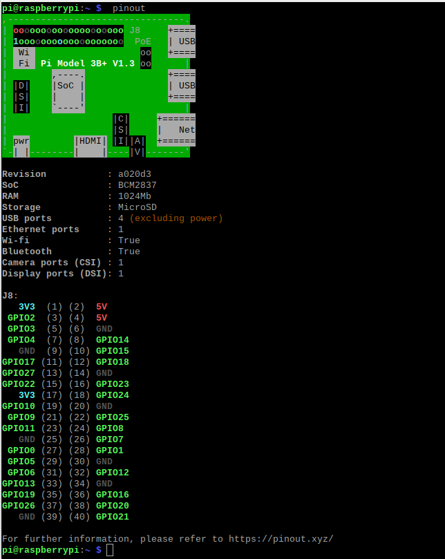
NOTE. The pinout command comes from the python library GPIO Zero. It only works if you have that library installed. E.g. Raspbian Buster Desktop has it installed per default but Raspbian Lite do not has it per default.
Here is another image, describing the same as the command pinout just did:
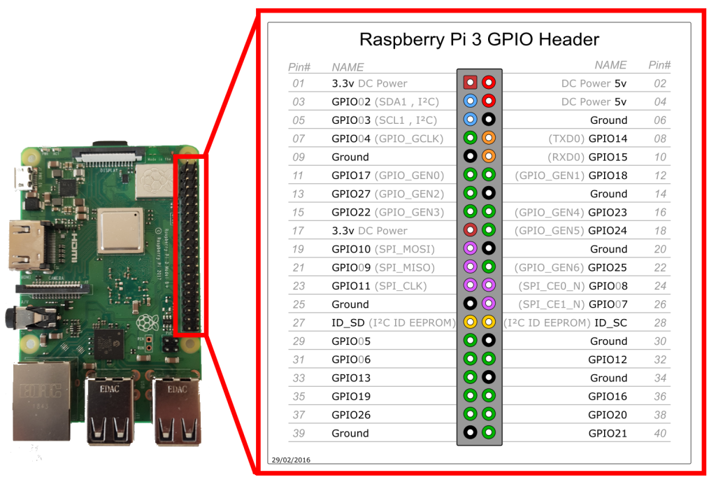
As you can see, there are two ways of naming the pins:
- When the number starts with 1, on the upper left pin and continuous counting to 40, this is called BOARD numbering.
- When the number starts with ‘GPIO’ followed by a number, this is called BCM or Broadcom numbering.
Info. Different programming libraries supports different conventions, so you need to read some documentation to see what the library and language you choose supports.
In this post, I will be showing two examples in python. One will be using the library RPi.GPIO, in this library you can choose between the two naming conventions. The second example will be using GPIO Zero, it is more suitable for beginners, but under the hood, it is doing the same as RPi.GPIO. In GPIO Zero, you can only use BCM mode.
Back to Index.
Setup
We will start with some wiring. We need:
- Dupont cables.
- LED
- 330 ohm resistor.
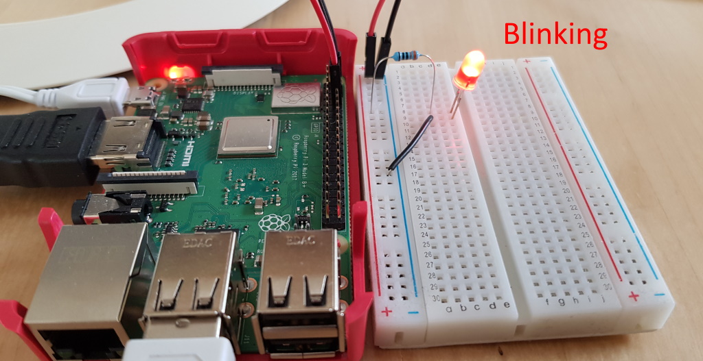
Here is the setup:
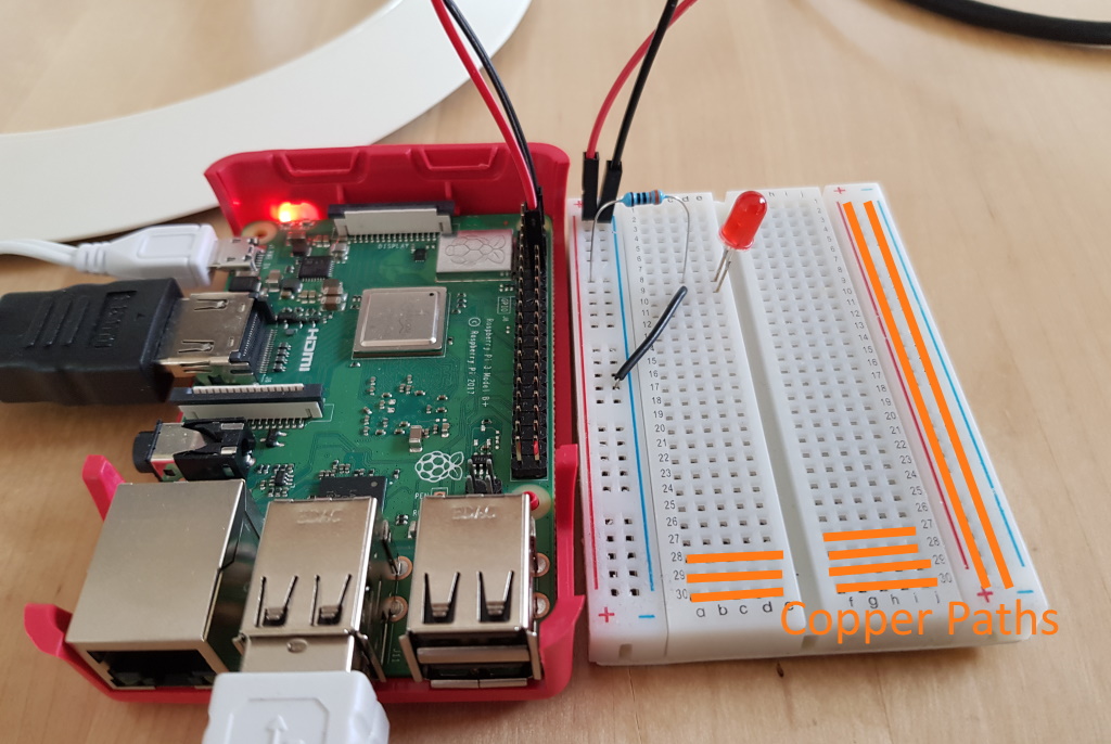
(The yellow lines shows how the copper paths inside the bread board are aligned.)
The Pi is feeding +5V through the red wire (pin GPIO14). Next is a 330-ohm resistor, standard when having +5V and a LED. Next is the LED.
Note that a LED always has a longer “leg”. That leg must be connected to the + side of the wiring. It is the Anode (+) of the LED. Current can only flow in one direction through the LED without damaging it.
Black wire is the ground.
Now we are ready for some coding!
Back to Index.
The Code
We will do all the coding from the terminal.
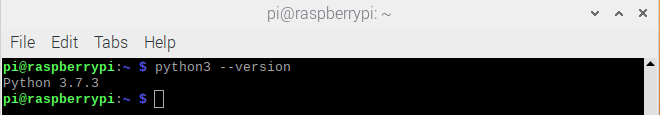
Raspbian Desktop comes with python3 preinstalled. You can check this by this command to print out the version:
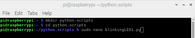
First, make a directory to save your python files. Move to that directory by the cd command. Now, execute the command sudo nano blinkingLED1.py this will open a terminal-based text editor that will allow you to edit and create the file blinkingLED1.py:
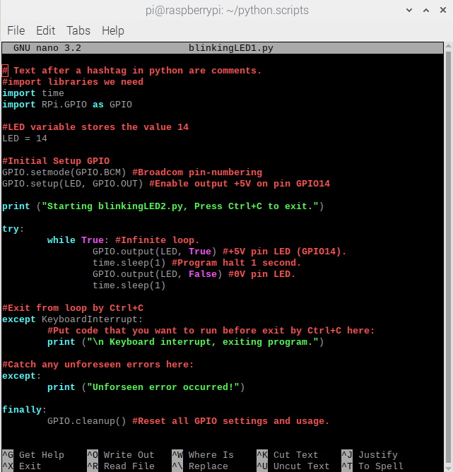
Here is the code for blinkingLED1.py:
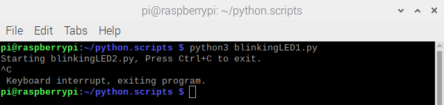
Here is how it looks like to start the program and stop it by Ctrl + C:
Some programmers have figured it out that this code (even if it is just a small piece) could be made even simpler and easier for beginners. So, they wrote the library GPIO Zero. This is how the exact same things looks like, written by using the GPIO Zero library instead of RPi.GPIO:
Much easier, isn’t it?
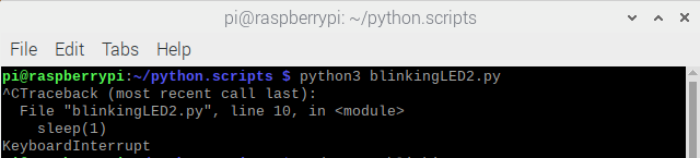
And this is how it looks like if you run it and stop it (Ctrl +C) from the terminal:
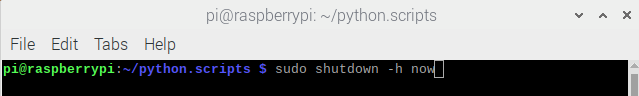
Note. When you are done, remember to always shutdown Pi properly, either from the GUI or with this command:
Here is the code of blinkingLED1.py:
blinkingLED1.py :
# Text after a hashtag in python are comments.
#import libraries we need
import time
import RPi.GPIO as GPIO

#LED variable stores the value 14
LED = 14

#Initial Setup GPIO
GPIO.setmode(GPIO.BCM) #Broadcom pin-numbering
GPIO.setup(LED, GPIO.OUT) #Enable output +5V on pin GPIO14

print ("Starting blinkingLED2.py, Press Ctrl+C to exit.")

try:
	while True: #Infinite loop.
		GPIO.output(LED, True) #+5V pin LED (GPIO14).
		time.sleep(1) #Program halt 1 second.
		GPIO.output(LED, False) #0V pin LED.
		time.sleep(1)

#Exit from loop by Ctrl+C
except KeyboardInterrupt:
	#Put code that you want to run before exit by Ctrl+C here:
	print ("\n Keyboard interrupt, exiting program.")

#Catch any unforeseen errors here:
except:
	print ("Unforeseen error occurred!")

finally:
	GPIO.cleanup() #Reset all GPIO settings and usage.
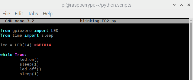
Here is the code of blinkingLED2.py:
blinkingLED2.py :
from gpiozero import LED
from time import sleep
led = LED(14) #GPIO14
while True:
	led.on()
	sleep(1)
	led.off()
	sleep(1)
Back to Index.
Conclusion
This post provided a simple example how to use the GPIO pins. Making a LED blink from one of your own programs can be considered a Hello world example of the GPIO usages.
Back to Index.
Resources
- https://www.raspberrypi.org/documentation/usage/gpio/ [2020-05-18]
- https://www.raspberryfield.life/2018/10/13/nespi-project-part-8-reset-button-and-reset-script/ [2020-05-18]
- https://www.raspberryfield.life/2018/11/03/arduino-basics-push-button/ [2020-05-18]
Back to Index.