Sega Mega Drive / Genesis 3-Button (A,B,C) Controller
In this post we will look at the Sega Mega Drive controller with the 3-button layout (A, B, C). The goal is to interface with it and convert the signals (protocol) to USB compatible keyboard presses. Then it is possible to use the original controller with a modern computer. For the conversion, I will program and use an Arduino Pro Micro board. To understand the Sega Mega Drive controller’s protocol, I will use a logic analyzer from Saleae.
TL;DR;
If the pin is LOW, the button is pressed (active low). Select is set by the host (the console).
| Select (Pin 7) | Pin 1 | Pin 2 | Pin 3 | Pin 4 | Pin 6 | Pin 9 | HIGH | Up | Down | Left | Right | B | C | LOW | Up | Down | * | * | A | START |
|---|
*) If these pins are set LOW together when SELECT is also low, it indicates that the 3-button controller is present.
Pin 5 = +5V and Pin 8 = GND.
Overview
- Prerequirements
- The Pinout
- The Controller
- Step 1 – Setup and Test
- Step 2 – Testing with custom extension cable
- Step 3 – Testing with logic analyzer
- About Glitch Readings
- Step 4 – The Readings – Overview
- Step 5 – Readings for each Button
- Step 6 – The Protocol Summary
- Arduino code (pseudocode)
- Last Comments
- References
Prerequirements
These blogposts can help you, if you find parts in this post too hard to understand:
- About Arduino push buttons and programming the Arduino board: https://www.raspberryfield.life/2018/11/03/arduino-basics-push-button/
- Reading and interface a Nintendo 8-bit, NES controller: https://www.raspberryfield.life/2018/09/01/nespi-project-part-4-the-nes-controller-protocol/
- Interfacing the Sega Master System controller: https://www.raspberryfield.life/2018/11/11/sega-master-system-controller/
Back to Overview.
The Pinout
The cable between the controller and the console is a RS-232 DB9.
This is the pinout:
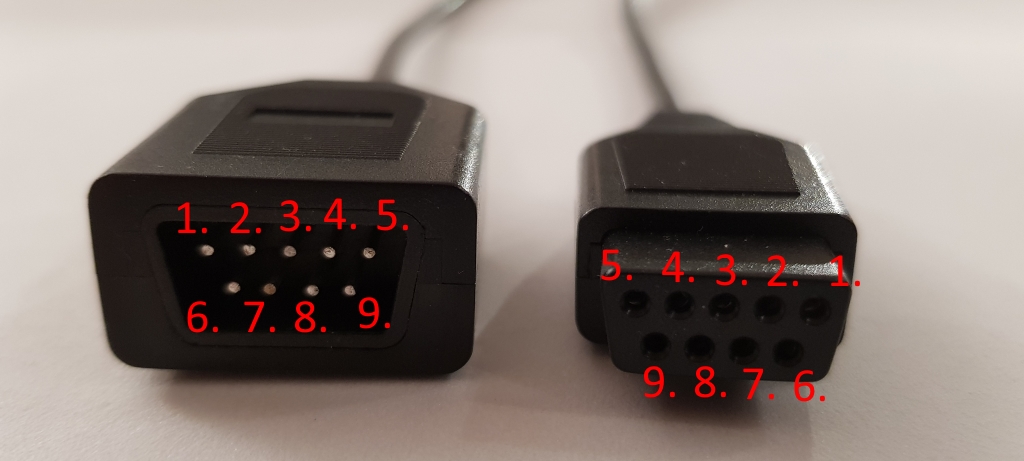
Note! Your cable/controller might have another colour scheme than presented in this post!
Pin 7 is the Select wire, it is controlled by the console (host). We will control it from the Arduino (our host) in this project. The select signal will toggle from Low to High repeatedly.
| Pin# | Select = Low (GND) | Select = High (+5V) | Colour Code | 1. | Up | Up | Brown |
|---|---|---|---|
| 2. | Down | Down | Red |
| 3. | Low(GND)* | Left | Orange |
| 4. | Low(GND)* | Right | Yellow |
| 5. | +5V | +5V | Green |
| 6. | A | B | Blue |
| 7. | Select | Select | Grey |
| 8. | GND | GND | Black |
| 9. | Start | C | White |
*) When the Select (Pin 7) is low AND Pin3 and Pin4 is low to, that indicates that a 3-button controller is plugged in.
Back to Overview.
The Controller
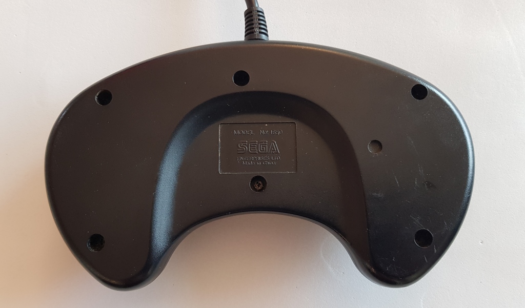
Sega Mega Drive 2 controller:

Six screws on the back:
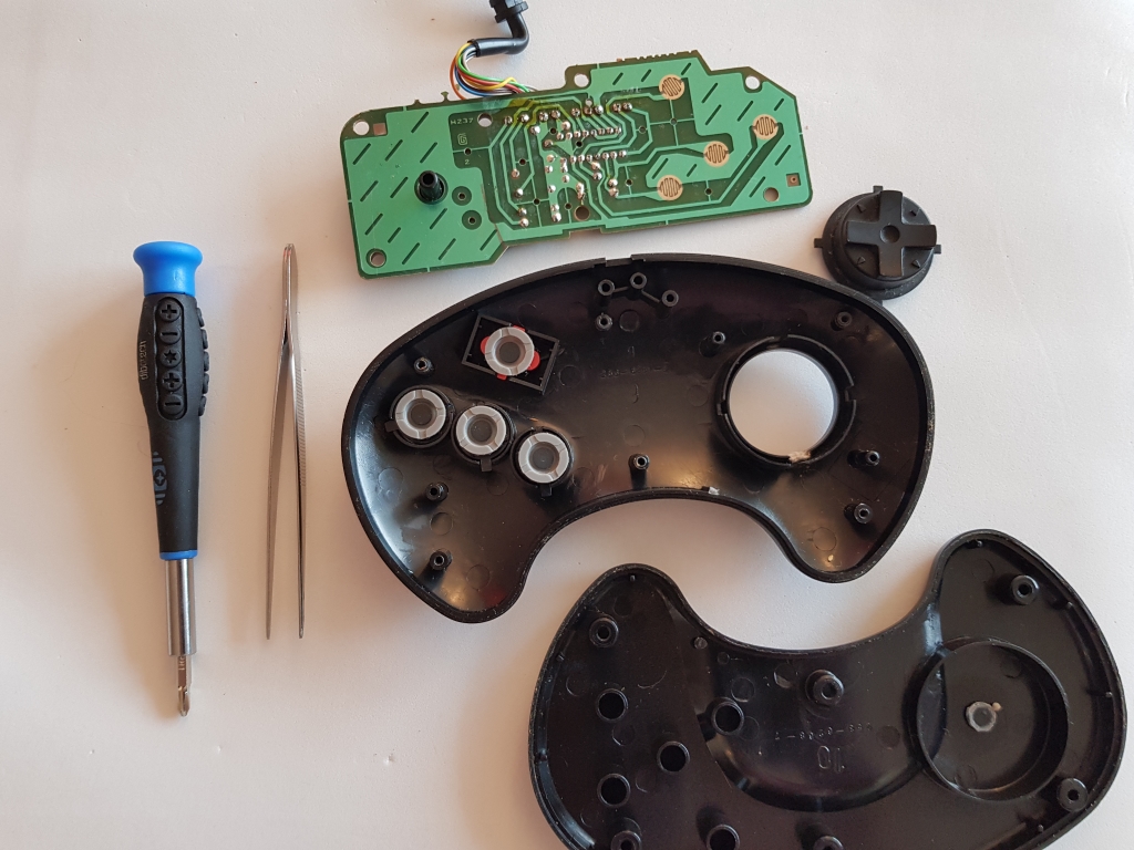
How it looks like inside:
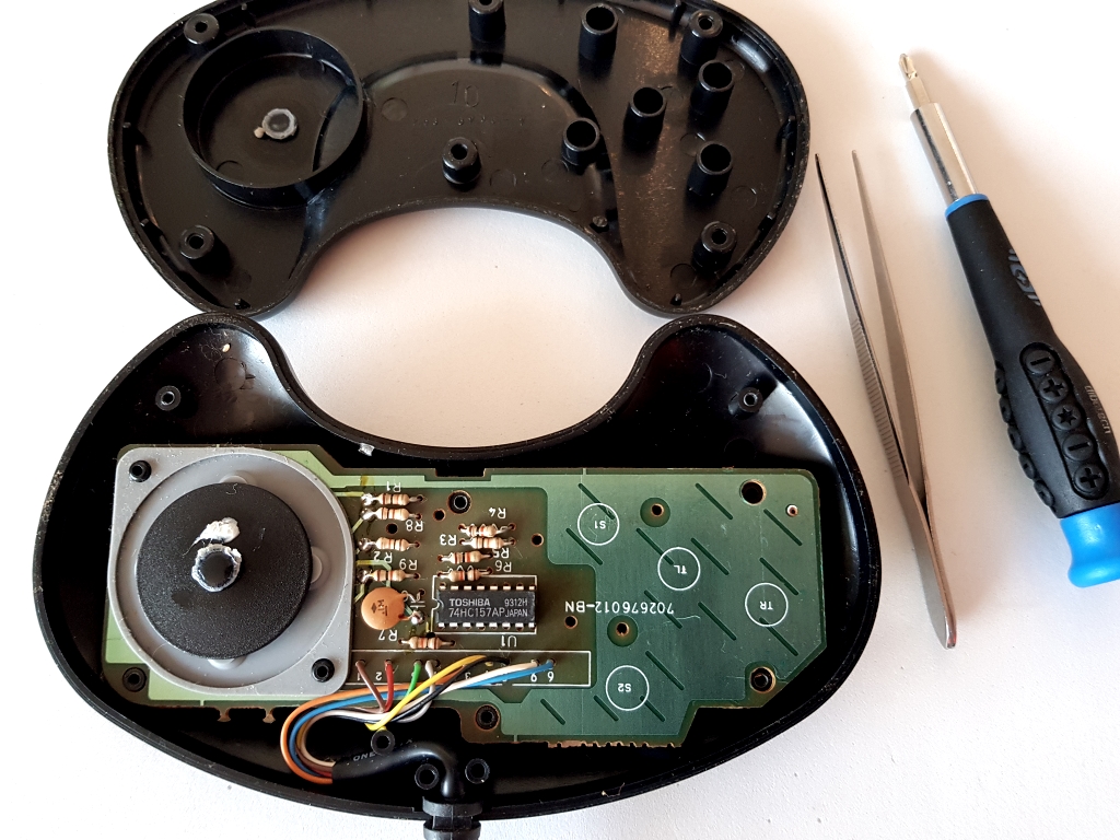
Info. Interestingly, the buttons for the D-pad is located under the PCB (Printed Circuit Board). On the button is a black plate with some grease on it. The plate is linked with a plastic tube to the D-pad. When you push the D-pad e.g. UP the plate tilts and presses the physical button under the PCB. I guess this mechanism makes the button presses smother when e.g. playing fighting games. I also think it makes it easier to press in diagonally directions.
Back to Overview.
Step 1 – Setup and Test
Setup your project and your “workbench”.
In every project you take on, the setup of the working environment is very important! Find a good space to work in and build up a positive atmosphere. Keep it nice and clean! I promise you, if you follow these simple rules, you will cut many hours in your project.
Here is my setup for this project:
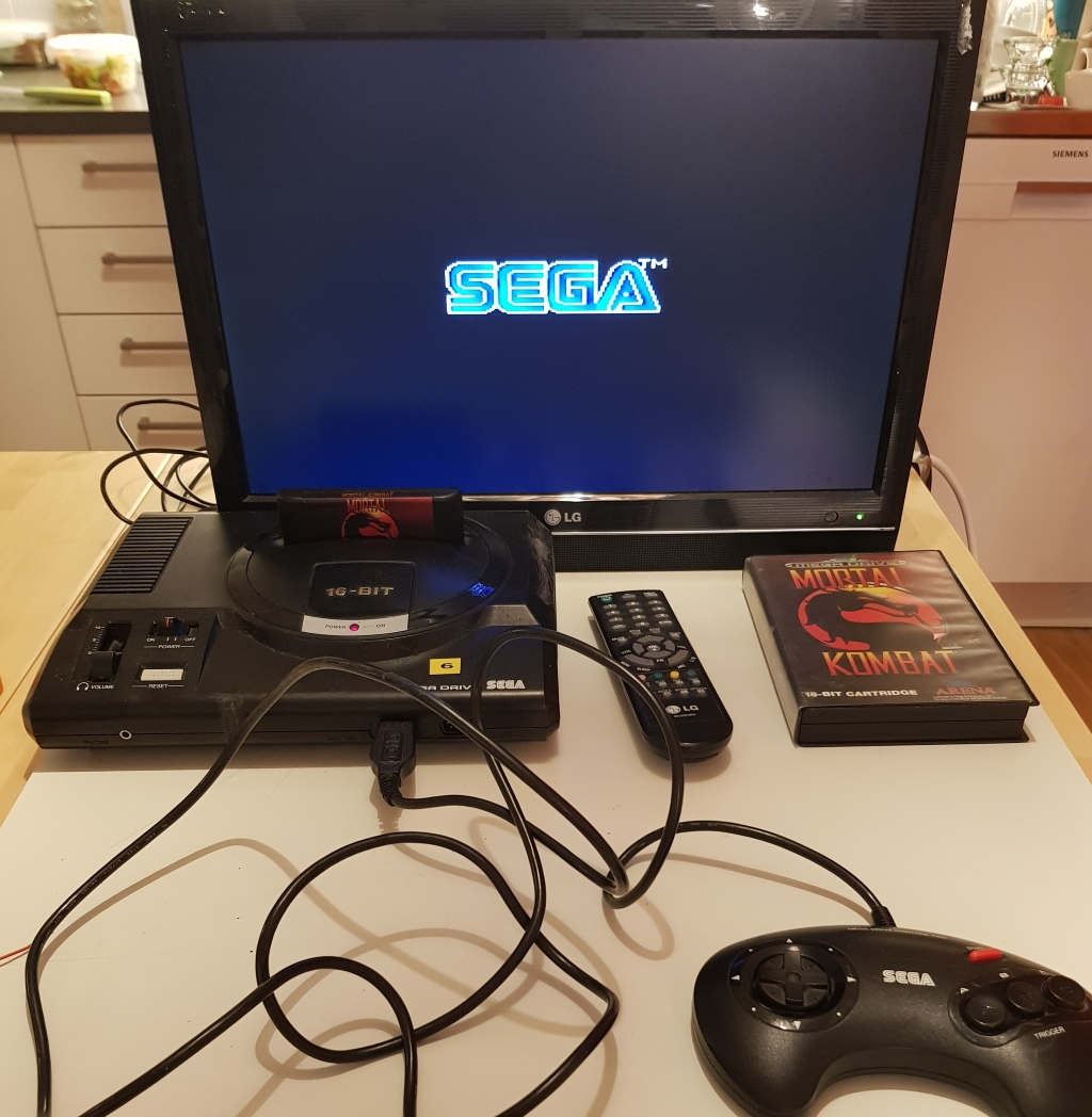
The first step here is to test a controller, to make sure that it is 100% working. Make sure that you pick a game that uses all the buttons, fighting games are often good for this purpose.
Back to Overview.
Step 2 – Testing with custom extension cable
Here is my test with an extension cable between the console and the original controller cable:
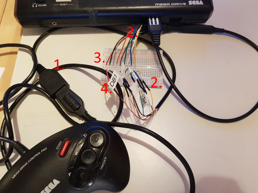
- Controller connected to the extension cable.
- With a multimeter set on continuity mode, I tested which wire goes to which pin. I also soldered aluminium wires to the copper wires, aluminium is easier to connect to a testing board like in the image above. The solder joints are covered with heat shrinking tubes.
- On one side of the extension cable I exposed the wires extra, so it is easier to connect the clips from the logic analyzer.
- To easier work with the cable, I labelled all the wires, which pin it belongs to. And never trust the colour scheme! The colour scheme in this after market wire is not the same as in the controller!
Back to Overview.
Step 3 – Testing with a logic analyzer
Here is everything setup for testing:
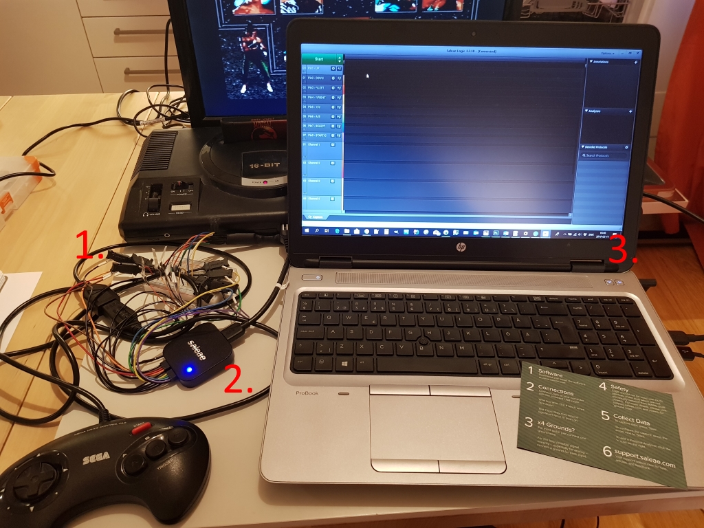
- Test probes are hooked up to each wire from the Saleae logic analyzer to the extension cable’s exposed wires.
- The Saleae Logic analyzer.
- The GUI from Saleae, desktop application.
Info. I bought a Saleae Logic Analyzer especially for projects like this. It’s simple to set up and the GUI you’re using with it is easy to install and understand. Saleae’s website is full of good documentation and easy to navigate. It’s a perfect tool for a hobbyist like me. One minor aspect I don’t like is that the probe cables can be mounted upside down. In the manual, it says that the ground cables go at the bottom. It would have been simple design to make that the cables can only be connected in one way.
Back to Overview.
About Glitch Readings
First time I did some readings, I got a lot of glitch readings. Glitch are noise in the circuit or from nearby electronics that are picked up by the logic analyzer. You can read more about it here. The Saleae GUI comes with a glitch filter.
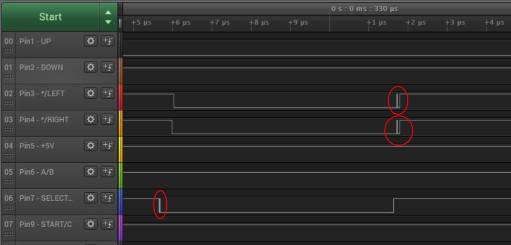
This is how glitch looks like (red circles):
This is how the reading looks like with glitch filter enabled:
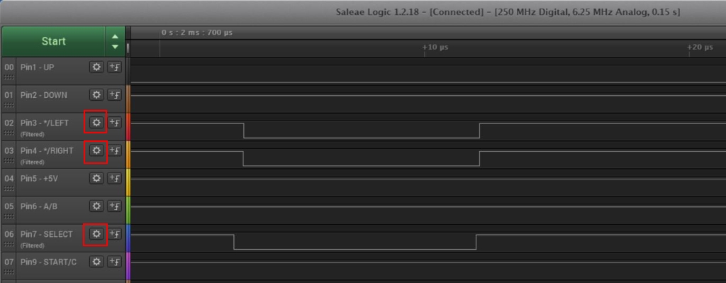
- You can enable glitch filter for each channel: Settings (red square) -> Enable Glitch Filter -> (I choose 1 micro second).
Back to Overview.
Step 4 – The Readings – Overview
The first overview reading looks like this:
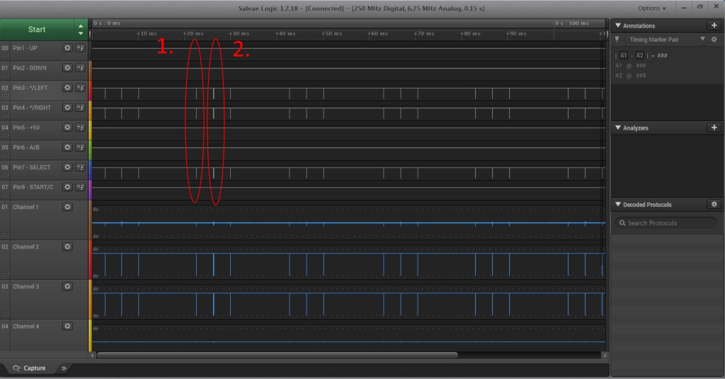
You can see that:
- Each ~22ms an activity on the wires starts.
- The activity is in intervals of three with ~5ms between them.
- You can’t really tell from the image above but, the first and third intervals are identically. The second, middle one (2nd circle) is different.
Let’s zoom in on the first circle:
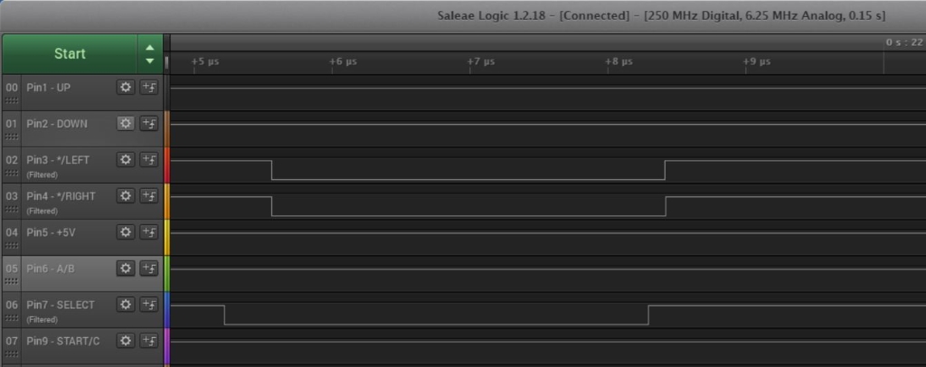
- One source I use for this blogpost says that: “When the SELECT wire is low and Pin3 and Pin4 is also low, that indicates that a controller is present.” And that is exactly what we can see in the image above!
Here is a zoom in on the second circle, the middle cycle:
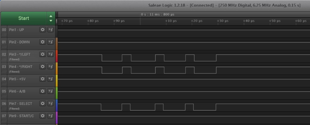
- Here we can see that the SELECT wire toggles four times very fast.
Info. I think that the game is actually doing this. It might be the way it is looking for if a 6-button controller is plugged in (a later blogpost). But the game I tested it with, Mortal Kombat, doesn’t have 6-button controller support? Well, this is very unclear for me. However, my goal is to interface with the controller and convert the signals to keyboard presses via an Arduino board. I can achieve this with just emulating the first cycles in the interval and everything should be fine. From now on, I will only focus my readings on the first cycle!
Back to Overview.
Step 5 – Readings for each Button
Only the UP-button pressed:
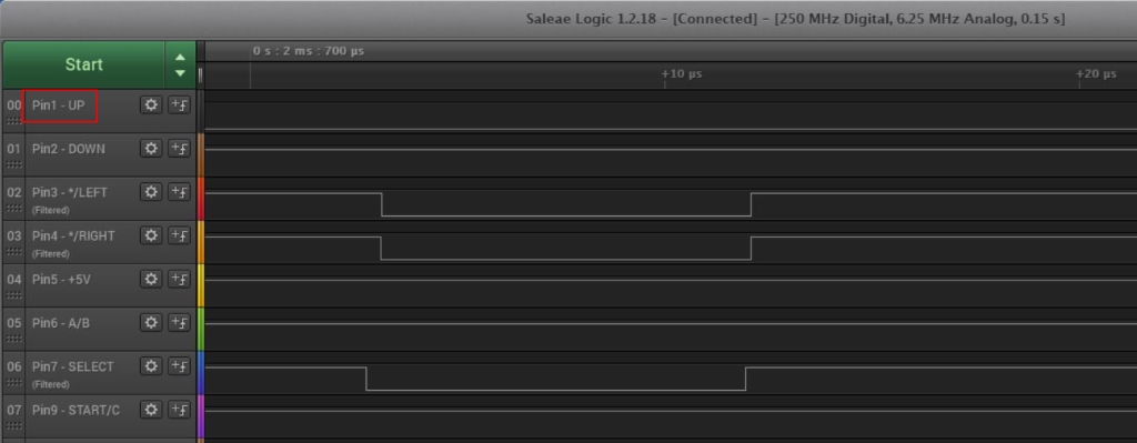
- The UP-button has its own wire. If it is low, the button is pressed.
The DOWN-button pressed:
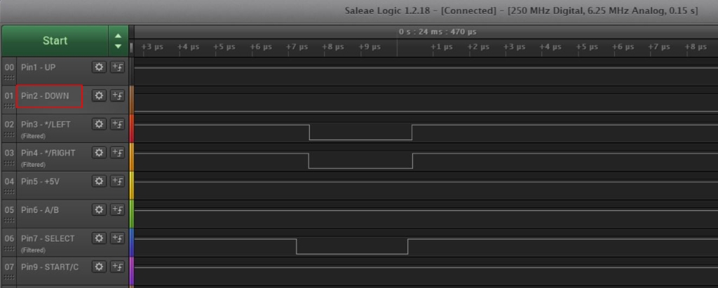
- The DOWN-button also has its own wire, if it’s low the button is pressed.
The LEFT-button:
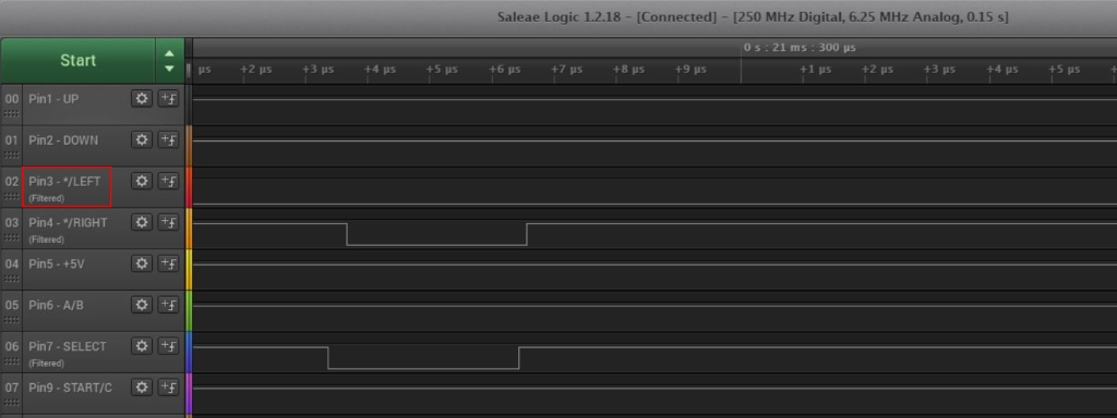
- When the SELECT is high, and the LEFT is low, the button is pressed.
Note, that you can’t read the state when the SELECT is low because the LEFT will always be low a that time, it’s part of the indication that a controller is present, remember?
The RIGHT-button:
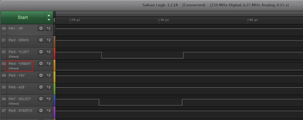
- Same logic as the LEFT-button.
The A-button:
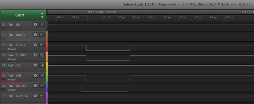
- If the SELECT is low and the pin6 A/B is low, the A-button is pressed.
The B-button:
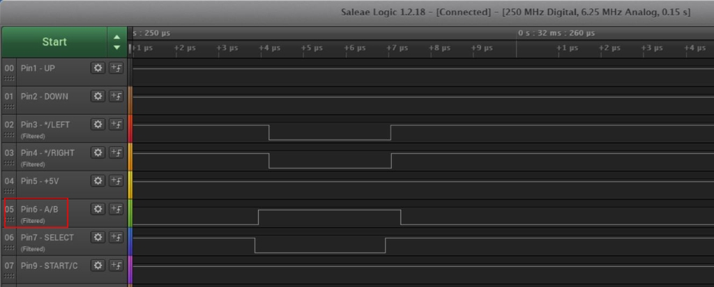
- If the SELECT is high and the pin6 A/B is low, the B-button is pressed.
The C-button:
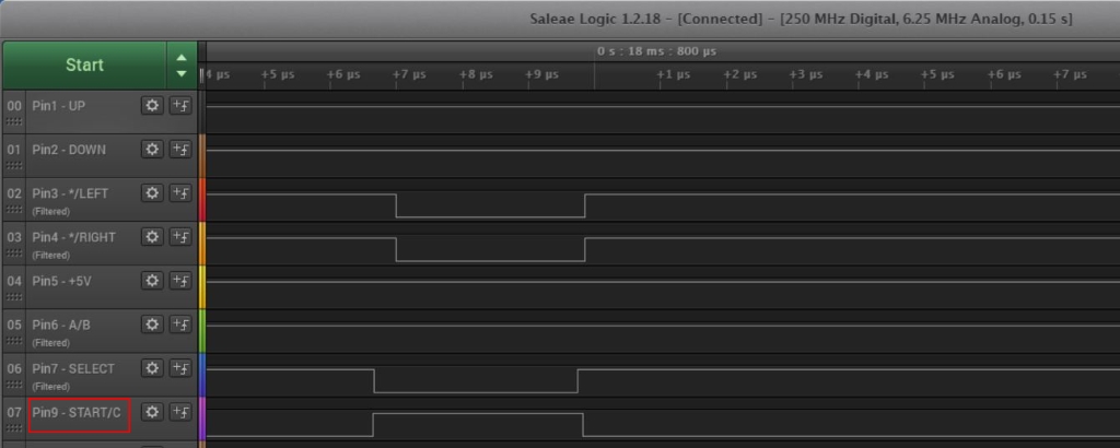
- If the SELECT is high and the Pin9 START/C is low, the C-button is pressed.
The START-button:
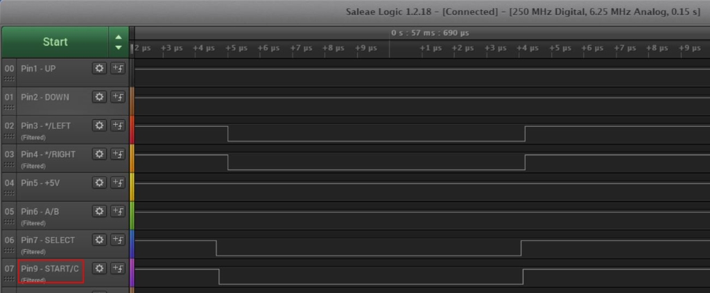
- If the SELECT is low and the Pin9 START/C is low, the START-button is pressed.
Back to Overview.
Step 6 – The Protocol Summary
This is the conclusion and summary from the readings:
If the pin is LOW, the button is pressed (active low). Select is set by the host (the console).
| Select (Pin 7) | Pin 1 | Pin 2 | Pin 3 | Pin 4 | Pin 6 | Pin 9 | HIGH | Up | Down | Left | Right | B | C | LOW | Up | Down | * | * | A | START |
|---|
*) If these pins are set LOW together when SELECT is also low, it indicates that the 3-button controller is present.
Pin 5 = +5V and Pin 8 = GND.
Back to Overview.
Step 7 – Arduino code (pseudocode)
This is a very simple example how to translate the protocol into code and keyboard emulation. I’m using an Arduino Pro Micro board that can emulate a keyboard.
Programming the board:
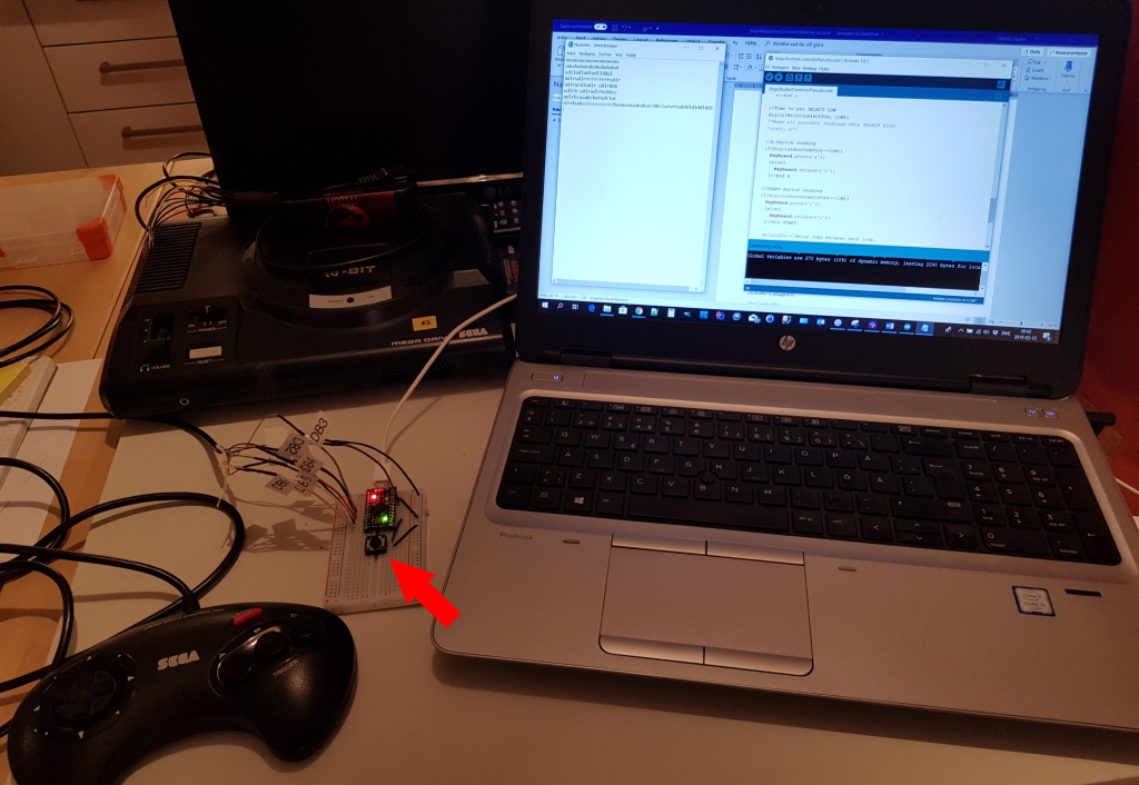
Note! I’m using a physical failover button (red arrow) when developing Arduinos that can emulate a keyboard. If I press the button, the code will go into a loop that does nothing. The reason for this is that if I write a bad piece of code, the board will take over the keyboard and in worse case, it will be impossible to change or delete it from the GUI.
Sega3buttonControllerEasyVersion.ino :
/*Interface with a 3-button Sega Mega Drive Controller,
 * easy (pseudocode) version
 * Converts button presses to keyboard strokes,
 *Raspberryfield.life 2019-02-13*/
#include <Keyboard.h>
const int builtInLedPinUno = 17; //Never used but good to know about.
const int stopPin = 15;
const int upPin = 2; //'u'
const int downPin = 3; //'d'
const int leftPin = 4; //'l'
const int rightPin = 5; //'r'
const int abPin = 6; //'b'when select high and 'a' when select low.
const int selectPin = 7;
const int startcPin = 8; //'c'when select high and 's' when select low.

bool stopButton = false;

void setup()
{
  pinMode(builtInLedPinUno, OUTPUT);
  pinMode(selectPin, OUTPUT);
  pinMode(stopPin, INPUT_PULLUP);//Note! Internal pull-up activated.
  pinMode(upPin, INPUT_PULLUP);
  pinMode(downPin, INPUT_PULLUP);
  pinMode(rightPin, INPUT_PULLUP);
  pinMode(abPin, INPUT_PULLUP);
  pinMode(startcPin, INPUT_PULLUP);
}
void loop()
{
  StopButton();//Check if failover button is pressed. Only for development.
  //Start by putting SELECT HIGH.
  digitalWrite(selectPin, HIGH);
  /*Make all possible readings when SELECT HIGH:
  *up, down, left, right, b, c*/
  //UP-Button reading
  if(digitalRead(upPin)==LOW){
    Keyboard.press('u');
    }else{
      Keyboard.release('u');
    }//End UP

  //DOWN-Button reading
  if(digitalRead(downPin)==LOW){
    Keyboard.press('d');
    }else{
      Keyboard.release('d');
    }//End DOWN

  //LEFT-Button reading
  if(digitalRead(leftPin)==LOW){
    Keyboard.press('l');
    }else{
      Keyboard.release('l');
    }//End LEFT

  //RIGHT-Button reading
  if(digitalRead(rightPin)==LOW){
    Keyboard.press('r');
    }else{
      Keyboard.release('r');
    }//End RIGHT

  //B-Button reading
  if(digitalRead(abPin)==LOW){
    Keyboard.press('b');
    }else{
      Keyboard.release('b');
    }//End B

  //C-Button reading
  if(digitalRead(startcPin)==LOW){
    Keyboard.press('c');
    }else{
      Keyboard.release('c');
    }//End C

  //Time to put SELECT LOW
  digitalWrite(selectPin, LOW);
  /*Make all possible readings when SELECT HIGH:
  *start, a*/

  //A-Button reading
  if(digitalRead(abPin)==LOW){
    Keyboard.press('a');
    }else{
      Keyboard.release('a');
    }//End A

  //START-Button reading
  if(digitalRead(startcPin)==LOW){
    Keyboard.press('s');
    }else{
      Keyboard.release('s');
    }//End START

    delay(20);//delay 20ms between each loop.
} //END Main Loop

/*Controll physical failover button
*The microcontroller emulates and takes over the keyboard.
*If you wrote bad code, it might be hard to actually change it,
*because it might prevent you from using the keyboard. This failover button stops
*unwanted behaviour from the keyboard library.
*/
void StopButton(){
  if(digitalRead(stopPin)==LOW){//(Active low)
    stopButton = true;
    }
  while(stopButton){
    Keyboard.releaseAll();
    Serial.println("---STOP Button pressed, program interrupted---");
    delay(1000);
  }
}//END StopButton()
The code isn’t perfect but easy to follow and it works! It is repetitive and make some unnecessarily function calls. I leave it up to you to further improve it.
The goal here is to make most people understand how the controller works, even if you are a beginner in the field of electronics.
Back to Overview.
Last Comments
I hope you enjoyed this post!
My goal now is to play Phantasy Star with the original controller, I want to play it emulated so I have save states. Now I have the nostalgic feeling and modern conveniences combined!
Info. Did you know that with the DB9 cable, and with the scheme/protocol of this controller, that it is backwards compatible with consoles like the Atari 2600 and the Sega Master System?
Back to Overview.
References
- PINOUTS.RU Sega Genesis joystick controller pinout http://pinouts.ru/Game/genesiscontroller_pinout.shtml [2019-02-11]
- GitHub jonthysell How to read Sega Controllers https://github.com/jonthysell/SegaController/wiki/How-To-Read-Sega-Controllers [2019-02-11]
- Jon Thysell Reading Sega Genesis controllers with Arduino https://jonthysell.com/2014/07/26/reading-sega-genesis-controllers-with-arduino/ [2019-02-11]
- Saleae What is a Glitch? https://support.saleae.com/tutorials/learning-portal/what-is-a-glitch [2019-02-12]